My initial inspiration for BlindSight came from another device developed by Alex Wulff called HaptoTech. In a presentation to my high school, Alex showcased the device, and I knew I wanted to redesign it and recreate it. Both devices use the general idea of an ultrasonic sensor sending ultrasonic waves to an object and receiving the waves back again. The device works because the code can compute a displacement from the time the wave traveled, neat! That was version one. Version two is what you see above. They are fairly comparable, but this version includes a custom PCB and a noise-making system. Version three will include a 3D-printed case and a strap, making it wearable.
Step One: The BrainsBlindSight version one uses an Arduino Uno R3, which is very standard in terms of hobby and maker projects. However, version two was upgraded and uses a microcontroller developed by Atmel known as the ATtiny85. It is no larger than one's fingertip and can be implemented into a custom PCB. The ATtiny85 comes in the DIP or SOIC 8 variants. The DIP can be easily mounted onto a PCB with a DIP 8 socket. The SOIC 8 is a smaller unit but can prove to be difficult to solder onto a PCB.
The Idea and device is useful for those who are visually impaired or completely blind. The idea is to leave the canes at the door and upgrade to a device like this. With these devices mounted, via a strap, over one's body, the user could map their entire environment with vibration amplitudes in their minds. The device could either replace canes entirely or supplement them, while decreasing user fear and increasing user confidence in prolonged movement.
Step Two: The CircuitThe circuit is relatively simple, and the circuit design is consolidated as much as it can be in terms of connections. Using an analog voltage pin on the ATtiny85, the current through the transistor's gate is proportional to the current through the vibration motor. Therefore, as the voltage at the gate increased (a larger analog voltage), the current through the motor would increase, and the motor would vibrate with a larger amplitude. This was the perfect design for this project because I could relate the displacement values to vibration amplitudes (a small displacement = a large vibration amplitude, as to alert someone that there is an object near their sensor). Additionally, if someone is very close to an object (displacement is programmable), a loud sound plays.
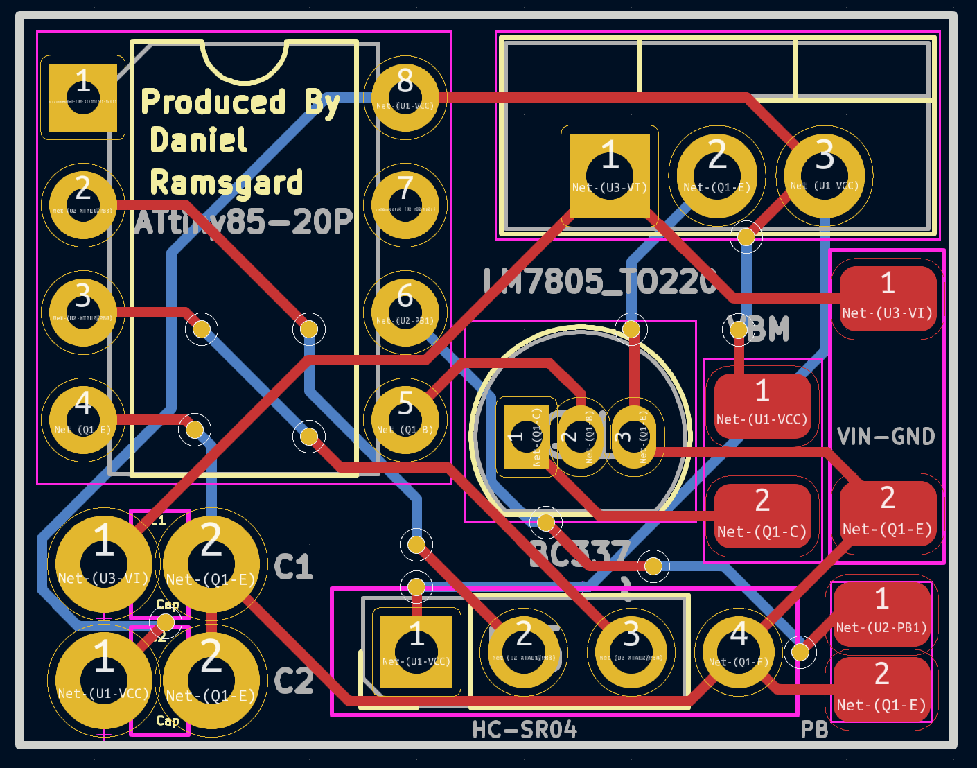
Step Three: AssemblyGoing from the breadboard version of this project to the PCB version takes a lot of careful soldering and precision testing. I would recommend allotting a few hours to this process, as mistakes are costly, and it's good to take it slow to avoid injury. Use the PCB layout image above as your guide through the soldering process.
Step Four: SoftwareThe software is relatively simple. Check it out in my linked attachments. Ultimately, the code initializes the device and begins the process of getting the HC-SR04 ready to send and receive data. After that, I have a computation process that returns a displacement based off of the speed of the waves and the time it took for the waves to return to the object. Furthermore, there is a switch-case block that assigns certain analog-voltage values to a certain pin to increase or decrease the amplitude of vibration of the motor. Also, in a certain case, a sound plays and vibration stops.
Step Five: Going FurtherCheck some of my other projects on my dashboard by clicking here.


_3u05Tpwasz.png?auto=compress%2Cformat&w=40&h=40&fit=fillmax&bg=fff&dpr=2)
Comments