


Hardware components | ||||||
| × | 1 | ||||
_ztBMuBhMHo.jpg?auto=compress%2Cformat&w=48&h=48&fit=fill&bg=ffffff) |
| × | 1 | |||
 |
| × | 1 | |||
 |
| × | 1 | |||
| × | 1 | ||||
 |
| × | 2 | |||
| × | 2 | ||||
| × | 1 | ||||
| × | 1 | ||||
| × | 1 | ||||
 |
| × | 1 | |||
| × | 1 | ||||
Software apps and online services | ||||||
 |
| |||||
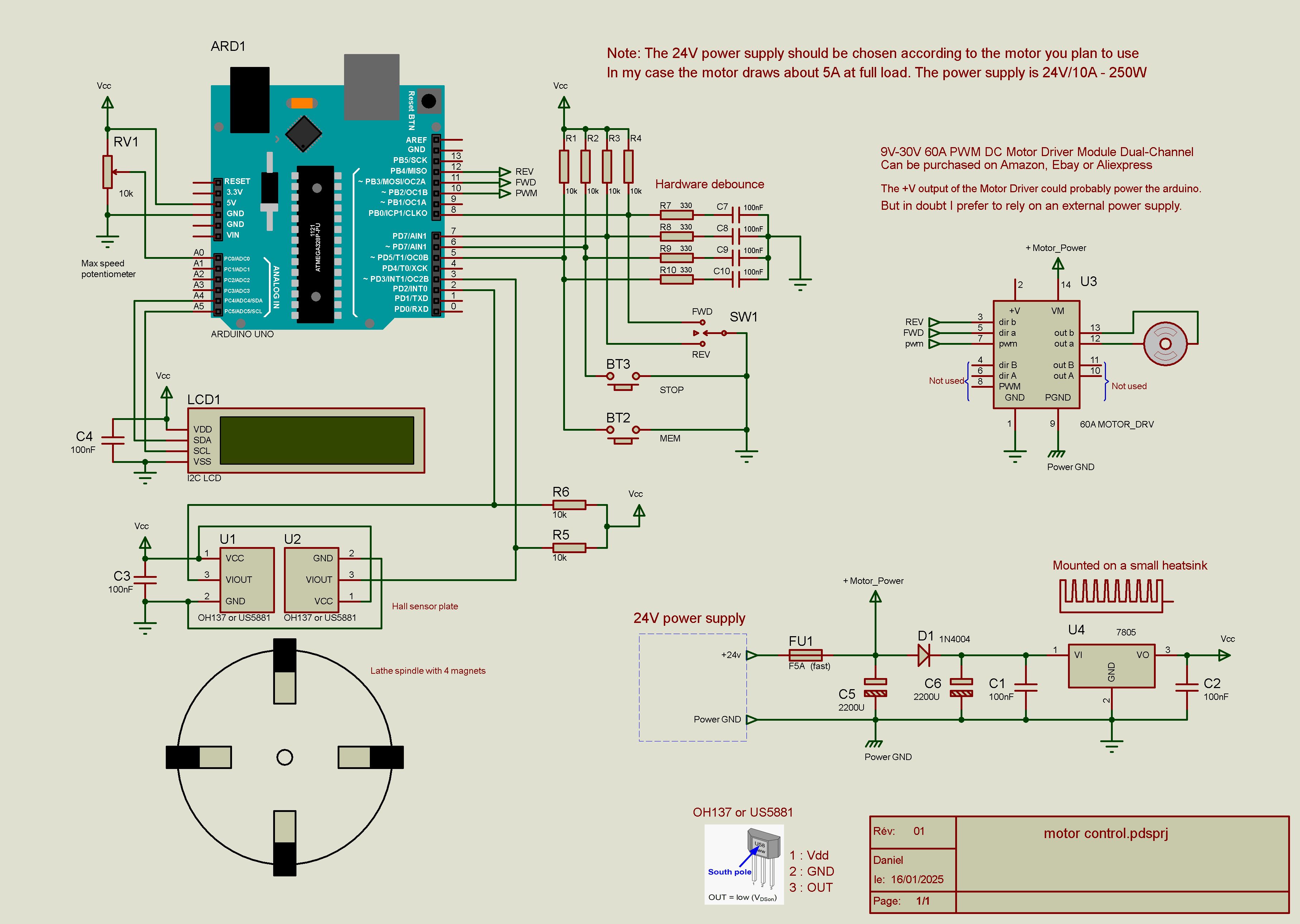
To make threads on a lathe one of the difficulties is to stop the rotation of the spindle precisely at the end of the thread. The lowest speed of my lathe is much too high. The first idea that came to me was to mount a windshield wiper motor. A pulley turned from a round piece of aluminum is attached to the motor shaft. A belt connects it to the second pulley groove of the original motor. Speed can now be throttled to a very low level. Since a PWM was needed to adjust the speed, another idea came to my mind: with an Arduino it would also be possible to memorize the forward and reverse positions and automatically stop the spindle rotation at the right position.
The motor assemblyThe wiper motor is mounted on a thick sheet of aluminium whitch I had laying around. Oblong holes allow the belt to be tensioned. For this a knurled screw at the top of the plate presses on the M10 threaded spacer.
Two M6 threaded rods and one M10 threaded rod equiped whith threaded spacer are screwed in to replace screws of the same diameter.
The M10 threaded spacer was machined from a copper bar while the M6 spacers where machined from a mild steel bar. Two flats on each part allow a spanner to be inserted for tightening. The four copper buttons around the main motor allow the auxiliary belt to be stored when not in use. This means that you do not have to touch the main belt to return the lathe to its initial configuration.
Below is what it looks like when assembled.
You can see the knurled screw at the top of the plate. It is used to tension the belt. The three thumbscrews are used to secure the plate.
There is a drawback if, like me, you let the belt on the main motor: with a permanent magnet DC motor, the motor will act as a generator if it is forced to rotate. The semiconductors in the lathe electronics short-circuit the motor and will brake it hard. To prevent this, you have to disconnect the motor. The direction of rotation reverser switch allows this if it is set to "0".
This disadvantage does not exist with asynchronous AC motors. They are braked by DC injection.
My lathe spindle is natively equipped with 4 magnets spaced 90 degrees apart to control the speed. These magnets can be used in conjunction with a Hall effect sensor to quantify spindle rotation. To determine the direction of rotation a quadrature sensor is required. Since quadrature Hall sensors are very expensive, two sensors are mounted on a perforated plate to create a quadrature sensor.
For a quadrature sensor it is important that there is an overlap between the signals. It is therefore necessary that the sensitive areas are as close as possible to each other. I tested sensors in SOT-23 and Flat TO-92 packages. The latter seemed easier to me to put the sensitive area as close as possible and have the required overlapping.
Both Hall sensors are mounted in opposition on a piece of perforated plate and immobilized with a drop of cyanoacrylate glue. Since the sensors output is open collector, a pull-up resistor is connected from the outputs to +5V rail. A bracket is fixed to the lathe allowing proximity adjustment with the magnets.
Below is the waveform of the two outputs for forward and reverse spindle rotation. The outputs overlap at about the half of the "LOW" state. Adjusting the distance between the sensors and the magnets allows to play on the relative waweform.
For testing all components were screwed onto a test plate. The LED bar graph you can see above the 4-line LCD screen serves me to visualize the outputs of the arduino. It is not necessary and does not appear on the schematic.
WARNING: The motor has a pole (the negative) connected to ground. It is necessary to cut the connection between ground and earth inside the power supply. Otherwise there will be a short circuit and the motor driver will be destroyed.
However a better solution would be to isolate the connection inside the motor if possible. Or to use another type of gear motor isolated from ground.
The softwareHow it should work (at least that's what I hope):
- If FWD or REV are pressed (and then released) :The motor continues in the desired direction until the memorized position and then stops (after reset the memorized position are default to 0 - 0 ).
- If FWD or REV are held down:The motor goes beyond the memorized position.It stops when the button is released
- If STOP button is pressed:The motor stops immediately
- If pressing the MEM and STOP buttons together:According to the last direction before the stop: - if FWD => the counter value is stored as forward limit - if REV => the counter value is stored as backward limit
If the motor rotates within the memorized positions, attempting to reverse causes the motor to stop and lock until the button is released. A short time delay (BRAKETIME) is added after the button is released.
Note that if the motor is manually forced to rotate outside the memorized limits with the FWD or REV button, reversal occurs without any brake pause. This may cause damage to electronics.
Remaining bugs:- Randomly displays a spurious speed
- The direction reversal lock may sometimes not work correctly
I could not find the reason why...


Comments