


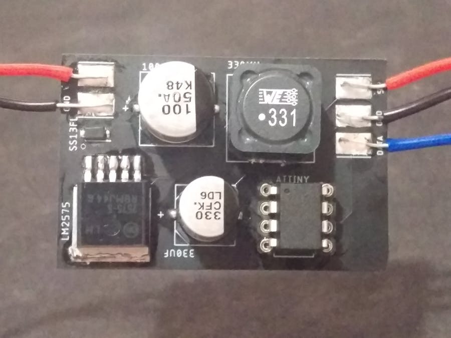

I wanted a board to run an LED ringlight using an ATtiny85, I also wanted it to run from the 24V PSU attached to my 3D printer, so I whipped up this board. It uses an LM2575 switching regulator to power the ATtiny85 (it will probably work with other types of ATtiny board) plus whatever else is connected to it, in my case a ring of LEDs. The switching regulator will deliver a maximum of 1 amp at 5 volts, so it can power quite a number of LEDs or whatever else you desire.
The images show version 0.1, upon recieving this board I thought that I could make a general use version that broke out all of the pins from the ATtiny. Below are the board layouts from EAGLE of version 0.2, I designed two variants of version 0.2, one with plain solder pads for wires as in version 0.1, I also made a version that uses screw terminals to make things a little easier.
I have attached zip files containing all of the required CAM data for having some of these boards made, I used JLCPCB, 10 of the boards cost me £3.95 plus £4.61 shipping.
I have also attached the brd and sch files so you can modify the design in EAGLE to suit your requirements.
There is also a bill of materials file for each version of the board, it is contained within the CAM data folder in the 'Assembly' directory as well.


_t9PF3orMPd.png?auto=compress%2Cformat&w=40&h=40&fit=fillmax&bg=fff&dpr=2)


Comments
Please log in or sign up to comment.