


Hardware components | ||||||
_ztBMuBhMHo.jpg?auto=compress%2Cformat&w=48&h=48&fit=fill&bg=ffffff) |
| × | 1 | |||
 |
| × | 1 | |||
| × | 1 | ||||
Software apps and online services | ||||||
 |
| |||||
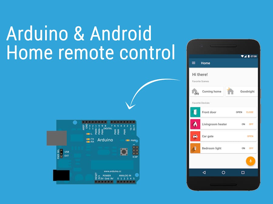
Everybody loves automation. Telling your home to turn the light on or enter your garage tapping on the screen of your phone are amazing stuff. At least, I think so.
That said, I decided to try to make my own system to control my home devices from my smartphone, without buying expensive third-party wifi adapter, smart bulbs or anythings like that; so, it had to be cheap, easy to use and had to be controlled from local and mobile internet connection. I know there are tons of excellent working projects out there (just to name some, Cayenne or the one by Anurag Vasanwala); anyway, I decided to make my own to fit perfectly my requirements. I focused my work on two main parts: the hardware setup and the development of a decent Android app.
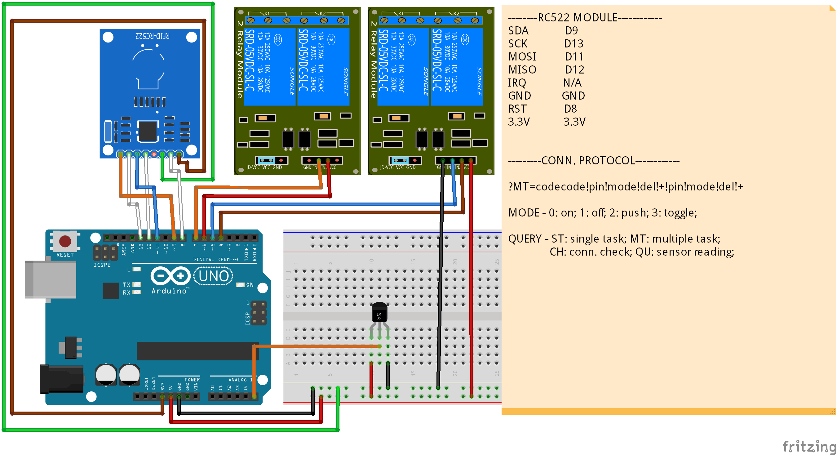
Hardware setupThe “hardware” is composed by three main components: Arduino, an Ethernet adapter and a relay board. All the devices I need to control - which at the moment are some lights, the car gate, the main door and the garage door - are hooked up to the relay board; the board is controlled by the Arduino, which is then connected via an Ethernet shield to my router. Additionally, I found a 2€ RFID reader, and decided to give it a try: it's now connected to the Arduino and allows me to open/close the gate using a RFID tag; unnecessary, but nice to have.
Here is how the finished setup looks like; pretty clean I think!
Communication protocolAll the instructions provided by the user inside the app are sent to the specified Arduino IP using the UDP protocol; the received string is then parsed and the desired device activated. The Arduino private IP and the router public IP are stored inside the app database; it's up to the application to decide which one to use, depending on the currently connected network. Once the Arduino has received the input, it sends back to the phone a confirmation code, to let the user know if the command has been run properly. The app also allows the user to input the router public IP in the form of an URL string: you can generate a unique URL using a dynamic dns service (such as no-ip.com) and register it in the router; this way you'll have a (sort of) static IP address, useful in the case your internet service provider doesn't provide you one - like mine.
In defining the communication protocol between the app and Arduino, the following requirements had to be taken into accounts: it had to tell Arduino which action to perform (turn on/off/trigger/simulate button pressure...) and on which pin and had to carry a unique id string to prevent malicious users to gain control of the house. The syntax I came up with is the following:
?MT=codecode!pin!mode!del!+!pin!mode!del!+Here ‘MT’ identifies a multiple action - or scene - and ‘codecode’ the 8 chars unique code. After the 8 chars code the first command string is sent; in case of a multiple action, more strings are sent using the ‘+’ char as a divider.
Surely somebody out there could do this way better, so if you have any suggestions about this feel free to post them, I’d be more than happy to improve the code.
User interface - Android appDesigning the app was another important point: I wanted it to be fully customizable, aesthetically pleasant and intuitive, for my family was going to use it. After designing and coding it, this is what it looks like:
Certainly not a professional one, but I’m quite happy with it!
The app provides:
- Single devices creation, like lights or door;
- Scenes (or “group actions”) which will run a list of predefined actions, based on existing devices;
- Customizable vocal commands;
- Multiple Arduinos management;
The Arduino sketch code is pretty simple:
- in checkUDP() the connection is checked; if any data is available it looks for the auth code, and once it has found it, the remaining string is sent to the corresponding processing method, depending if it is a single action, a multiple action (or “scene”), a connection check request or a sensor reading request.
- in checkRFID() Arduino checks the RFID reader; if any card is found, the read code is compared to the authorized ones and, if it is found between them, the corresponding action is launched.
- homotica.refresh() tells the homotica library to check if enough time has passed for a certain pin to be pulled high or low; this is set when the user send a “push” command; the library is available on Github (link at the bottom of the page).
Here is the sketch code; as I said, suggestions are the welcome!
Future developmentI'm planning to keep the development going, at least on the app side, for I'm quite pleased with how this project came out. I’d like to add, in the near future, the following features:
- Time & location-based triggers
- Sensor readings & data processing
- Real time Arduino-to-app notifications
If you would like to take a look to the app, feel free to try it out; I made it available on the play store at this link. However, remember it's the first release,
Thank you for reading, have a good day! ;)
Dave


Comments
Please log in or sign up to comment.