This project is an attempt to use the SparkFun RedBoard Artemis ATP board for Industrial Environment Monitoring and Control application. Normally, the monitoring and control of industrial spaces are managed by complex systems. They are not only expensive but also difficult to customize or maintain. The Industrial Environment Monitoring and Control using SparkFun RedBoard Artemis ATP not only provides safety, robustness, and scalability but also ease of access and control. In all the plants, maintaining an optimal environmental condition is always preferred.
WorkflowThe system takes advantage of SparkFun RedBoard Artemis ATP.
Pin mapping is as follows:
The SparkFun Qwiic Environmental Combo Breakout which continuously monitors the industrial space for variations in the environmental conditions using the Sparkfun Environmental Combo breakout board, connected via Qwiic interface.
The CCS811/BME280 (Qwiic) Environmental Combo Breakout works together to take care of all the atmospheric quality sensing needs with the CCS811 and BME280 ICs. The CCS811 provides readings for equivalent CO2 in the parts per million (PPM) and total volatile organic compounds in the parts per billion (PPB). The CCS811 also has a feature that allows it to fine-tune its readings once it has access to the current humidity and temperature. The BME280 provides humidity, temperature, and barometric pressure. This allows the sensors to work together to give us more accurate readings than they'd be able to provide on their own.
The CCS811+BME280 communicates exclusively via I2C, utilizing the Qwiic system using the 4-pin polarized Qwiic connectors. Together the sensors can consume 13 mA of current. It takes 12 mA to power the CCS811 while 1 mA to power the BME280. The various characteristics and Range are as follows:
- Operating Voltage : 3.3V: Regulated to 1.8V - 3.6V
- tVOC : 0 - 1187 PPB
- eCO2 : 400 - 8192 PPM
- Temperature : -40°C - 85°C
- Humidity : 0 - 100% RH, ±3% from 20 - 80%
- Pressure: 30 - 110 kPa, relative accuracy of 12 Pa, absolute accuracy of 100 Pa
- Altitude : 0 - 30, 000ft (9.2km), relative accuracy of 3.3ft (1M) at sea level, 6.6ft (2M) at 30, 000ft.
The I2C address can be changed using the jumpers on the back of the board if multiple devices with the same I2C address are used. ADR1 can be used to change the I2C address of the CCS811 from 0x5B to 0x5A by adding solder to close the jumper. The ADR2 jumper can be used to change the I2C address of the BME280 from 0x77 to 0x76. The I2C bus has pull-up resistors enabled by default. If not desired, these can be removed by separating the "I2C PU" triple jumper on the bottom side with a hobby knife. The locations of these jumpers are shown in the picture below.
Note: The BME280 is unable to compensate for the heat produced by the CCS811. This can cause the displayed temperature to be up to 15° higher than the actual ambient temperature. To compensate for this take the difference between an initial temperature reading (with a cold sensor) and a final temperature reading (after letting the sensor warm-up). Then subtract this value from `BMEtempC` to ensure the proper calibration is taking place.
The Qwiic Proximity Sensor is a simple IR presence and ambient light sensor utilizing the VCNL4040. This sensor is excellent for sensing objects in front of the sensor, qualitatively up to 20cm away. The VCNL4040 is a proximity sensor (PS), an ambient light sensor (ALS), and a high power IR emitter (IRED) integrated into a single package. The ambient light sensor and proximity sensor operate in a parallel structure. The combination of the two sensors along with the IR emitter forms the proximity detector. The VCNL4040 has no dead zone and can read all the way up to the face of the sensor. The SparkFun Proximity VCNL4040 sensor is a great digital alternative to the popular analog PIR sensors. The Qwiic Proximity Sensor also has an ambient light sensor built-in.
The IR emitter is immune to red glow with a 940 nm wavelength (for those discrete applications) and the sink current is programmable (200 mA default). The VCNL4040 offers a 16-bit high-resolution ALS with ±10 % accuracy and is immune to fluorescent light flicker. With an ambient light sensing capability down to 0.01 lux/step, the VCNL4040 works well under a low transmittance lens design (dark lens). In addition, the patented FiltronTM technology offers great background light cancellation capability (including sunlight) without utilizing microcontroller resources. The proximity sensor features smart persistence, which prevents the misjudgment of proximity sensing but also keeps a fast response time. In the active force mode, a single measurement can be requested for more design flexibility and/or power saving.
Note: This Proximity Sensor is excellent for detecting qualitative changes (if an object is there or moved since the last reading), but unsuitable for quantitative distance readings.
Using the Proximity Sensor, the system detects an operator in close proximity.
Warning: All pins are 3.3V. So DO NOT expose the pins to 5V and the ADC on the Artemis is 0-2V. Exposing an ADC pin to 3.3V will not harm the device but the ADC will saturate returning 16,383 (14-bit) for voltages greater than 2V.
In our project, the sensors are connected via the Qwiic I2C interface. The I2C pins on the Artemis are labeled SDA and SCL. They are controlled in the Arduino IDE using Wire.begin(), Wire.read(), etc. The same SDA/SCL pins are connected to the Qwiic connector for using in the SparkFun's Qwiic ecosystem.
Note: The standard Arduino has SDA/SCL additionally connected to A4/A5. A4/A5 on the Artemis are not I2C related, they are only Analog. SDA/SCL are digital pins 14/15 respectively. A4/A5 can be used as digital pins 20/21 respectively.
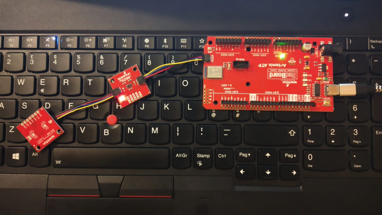
All the sensors are connected in series using the standard Qwiic I2C interface as shown below.
- In Arduino, open the Preferences menu item. File > Preferences,
- Add the following path to the Additional Boards Manager URLs: path in preferences.
https://raw.githubusercontent.com/sparkfun/Arduino_Boards/master/IDE_Board_Manager/package_sparkfun_index.json - Select the OK button to save your preferences.
- Once the location of the SparkFun board package is set in the preferences, the board definition package for the SparkFun Apollo3 boards must be installed.
To install the package, use the following steps:
- In Arduino, open the Preferences menu item. Tools > Board "..." > Manage Boards...
- Search for SparkFun
- Select the **SparkFun Apollo3 Boards" package
- Close the dialog
- Select the SparkFun Edge Board. Tools > Boards "..." > SparkFun RedBoard Artemis ATP
- Set the Bootloader to the SparkFun Variable Loader. ***Tools > Bootloader "..." > SparkFun Variable Loader..."
- Download (or clone) the Arduino file.
https://github.com/crisdeodates/Deodates-Projects/blob/master/SparkfunAI.ino
- Open Arduino
- Open the sketch from this repo through Arduino by clicking on a
.inofile - Select the
SparkFun RedBoard Artemis ATPboard (Tools->Board under 'SparkFun Apollo3') - Select the proper port to connect with the board (Tools->Port)
- Windows - COM Port
- Linux - /dev/ttyUSB*, where * is a number.
NOTE: Permissions on this device needs to include user read and write (chmod 666)
- macOS - /dev/cu.usbserial*
- Select the proper port to connect with the board (Tools->Port)Windows - COM PortLinux - /dev/ttyUSB*, where * is a number.
- macOS - /dev/cu.usbserial*
- Change the Bootloader from Ambiq Secure Bootloader (Default) to SparkFun Variable Loader (Enable w/ Artemis Bootloader) (Tools->Bootloader)
- Change the
SVL Baud Ratefrom 921600 to 230400 - Compile with the
Verifybutton (checkmark symbol) - Upload with the
Uploadbutton (arrow symbol) - If uploading fails try lowering the bootloader baud rate
- Upload with the
Uploadbutton (arrow symbol) - If uploading fails, try lowering the bootloader baud rate
Note: The warnings if any from the compiler can be ignored.
- The bootloader attempts to upload 3 times. If all three attempts fail, try adjusting the baud rate.
- Open the Serial Monitor by clicking on the magnifying glass icon (top right) or (Tools->Serial Monitor).
For keyword detection, setup, I have referred to the work by javagoza. Find the details in the reference section.
TestingWhen an operator is detected, the system will then enter a listening mode where the commands provided by the operator will be used for overriding any specific conditions. In case of an emergency, thanks to the machine learning capability of the system. The command is received via the inbuilt microphone enabling low power voice recognition. In the event of an unfavorable condition, with the help of a suitably trained TensorFlow model, RedBoard Artemis ATP understands the urgency and type of action required to regain the optimal environmental conditions by controlling the various modules attached. The appropriate relay is activated/deactivated for the control. The pre-trained model can detect either 'YES' or 'No'.
Challenges faced- Training anew model for keyword detection require additional dedicated computational resources.
https://www.hackster.io/contests/sparkfun
https://learn.sparkfun.com/tutorials/hookup-guide-for-the-sparkfun-redboard-artemis-atp


_3u05Tpwasz.png?auto=compress%2Cformat&w=40&h=40&fit=fillmax&bg=fff&dpr=2)
Comments