Context
This project aims to develop two use cases of Sigfox technology.
Use-case 1: Automated energy monitoring and analysisPresently, electrical energy consumption from users in an area is monitored and calculated by frequent field visits done by technicians from the electricity department for the calculation of energy fare. This is a time-consuming task as there will be thousands of houses in an area and numerous apartments in the same flats. When it comes to a city or town, this is a very hectic process. There is no provision to check or analyze the individual energy consumption of houses in a period of time nor to create a report of energy flow in a certain area. This is just the case throughout many places in the world.
There are no existing solutions implemented to tackle the above problem. We are proposing a smart energy monitoring system that will ease the inspection, monitoring, analysis, and calculation of energy fare. The proposed system will additionally allow generating user-specific or area-specific charts and reports to analyze the energy consumption and energy flow.
Use-case 2: Automated digital surveyManufacturers and third-party vendors normally use manual or digital surveys to analyze the usage and customer satisfaction levels of their products. The whole process can be automated using Sigfox technology.
A Sigfox centered smart solution allows various manufacturers and third-party vendors to carry out usage analysis and customer level satisfaction index of their products autonomously. In addition to standalone operation for multiple years, the solution comes with all the advantages of Sigfox including low cost and low power, portable and compact.
WorkflowSigfox technology at a glance
Sigfox is an LPWA (Low Power Wide Area) network that allows objects to communicate to the Internet for years because of its very low battery consumption. Sigfox communications support up to 140 uplink messages a day, each of which can carry a payload of 12 Bytes (Excluding message header and transmission information) and up to 4 downlink messages per day, each of which can carry a payload of 8 Bytes. Sigfox offers a software-based communications solution, where all the network and computing complexity is managed in the Cloud, rather than on the devices. All that together, it drastically reduces energy consumption and the costs of connected devices.
Features: (Ref: https://www.sigfox.com/en/sigfox-iot-technology-overview)
- Ultra Narrow Band radio modulation
- Lightweight protocol
- Small payload
- Star network architecture
- Design choices and benefits
Setting up the MKRFOX 1200
- 1. Install the Arduino IDE
- 2. Install the MKRFox1200 Arduino core from the "Boards Manager". search Zero or MKRFox to find the core. Click on its box and click on the install button. On the bottom bar of the window, you can follow the download and install procedure, including the installation of the proper driver, needed by the operating system to use the board.
- Select the MKRFox1200 board and port.
Setting up the SigFox's backend
- Connect your board to your computer and flash the MRKFox1200 example named "FirstConfiguration"
- Open the monitor terminal and write down the ID and PAC
Tip #Press the "RST" button if the board is undetected in PC.
- To register your board, navigate to the SigFox backend.
- Select the country where the user is residing or using it right now
- Enter your ID and PAC number which was shown on the serial monitor after uploading the sketch the FIRST CONFIG.
- Input your credentials to get to the Sigfox portal home page.
- Click on the Device type -> Keep Alive -> Edit -> Set Downlink mode to Direct to receive messages back and forth.
- Go back to the main Sigfox portal page and click on the Device on Top left, then click on the ID as shown in the image below
- Select the messages item on the left menu bar. If it is sent properly, then you can see the green call back otherwise, you can see callback as a red arrow
Sigfox radio protocol
Sigfox is an LP-WAN communication technology and network dedicated to IoT. That is, Low Power communication (25mW) and a Wide Area Network coverage (60km).
Sigfox uses DBPSK encoding for its communication. The Sigfox message frame format consists of the following blocks.
We are only interested in the Payload section which varies from 4 to 12 bytes. This area contains the data transmitted. The information is compressed and not directly readable.
Arduino MKRFOX 1200
MKRFOX1200 is a powerful board that gives the functionality of the Zero but the connectivity of the SigFox network.
Use-case 1: Automated energy monitoring and analysisThe Sigfox module is given a unique user code to identify the particular housing unit or area where the energy consumption has to be measured. The power consumption will be monitored with the help of a convenient current sensor interfaced using the analog connection.
The energy consumption data, the unique user code and the location (fixed for each device) of the module will be uploaded to the Sigfox network periodically. The data from the network can be accessed and analyzed to calculate individual energy consumption, generate individual and collective energy charts, generate energy reports and for detailed energy inspection. The whole area under consideration will be divided into cell blocks inside the Sigfox network for easy management of data as shown below.
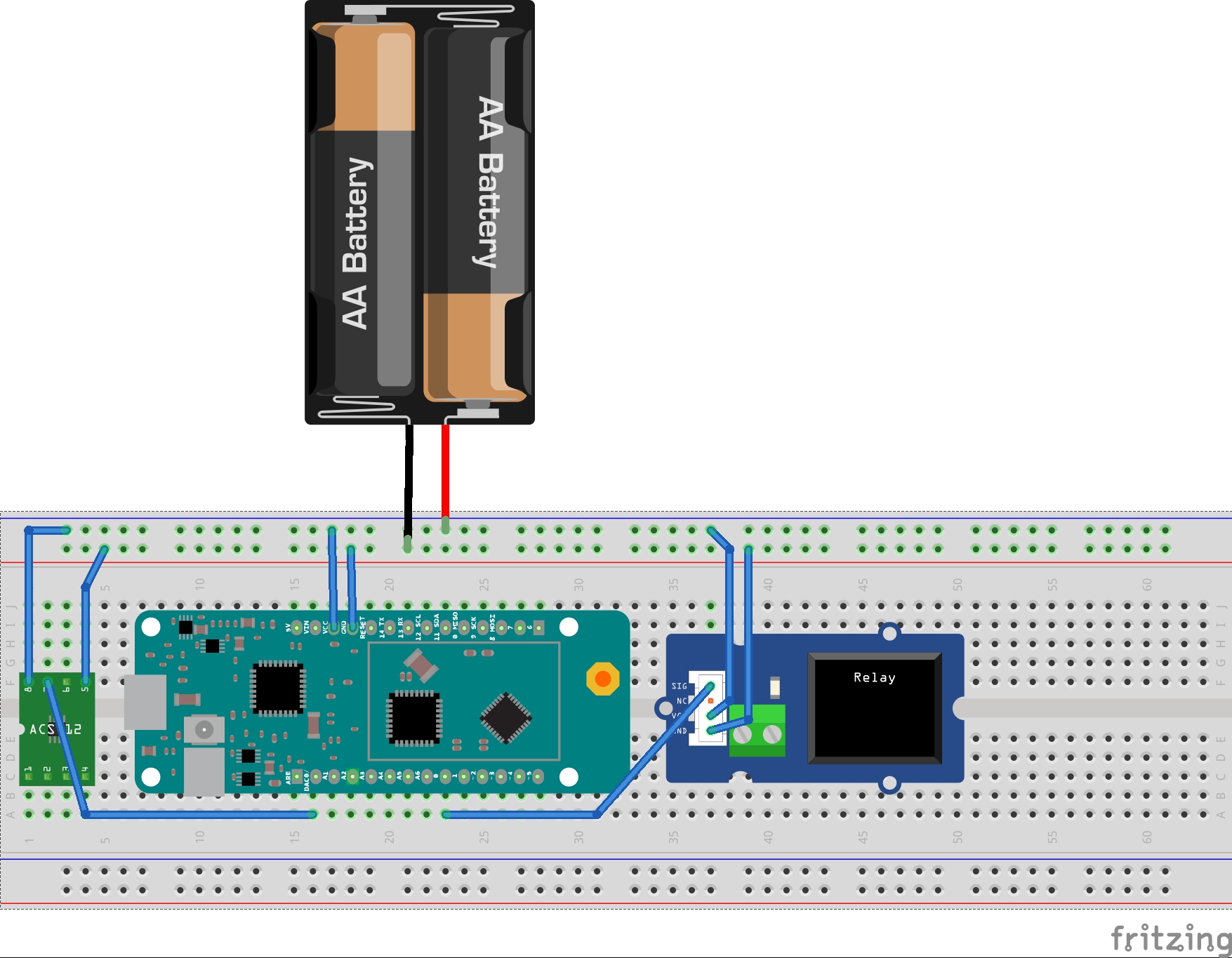
The interfacing diagram is as follows.
Power from the AC mains is drawn and passed through the current sensor which is integrated into the household circuit. The AC current passing through the load is sensed by the current sensor module and the output data from the sensor is fed to the analog pin of the Sigfox module. Once the analog input is received, the measurement of power/energy is inside the program. The calculated energy is then published to the Sigfox network.
Circuit Setup
Real Power (P): This is the power used by the device to produce useful work. It is expressed in kW.
Real Power = Voltage (V) x Current (I) x cosΦ
Reactive Power (Q) : This is often called imaginary power which is a measure of power oscillates between source and load, that does no useful work.It is expressed in kVA.
Reactive Power = Voltage (V) x Current (I) x sinΦ
Apparent Power (S) : It is defined as the product of the Root-Mean-Square (RMS) Voltage and the RMS Current. This can also be defined as the resultant of real and reactive power. It is expressed in kVA
Apparent Power = Voltage (V) x Current (I)
Relation between Real, Reactive and Apparent power:
Real Power = Apparent Power x cosΦ
Reactive Power = Apparent Power x sinΦ
We are concerned only on the Real power for the analysis.
Power Factor (pf) : The ratio of the real power to the apparent power in a circuit is called the power factor.
Power Factor = Real Power/Apparent Power
Thus, we can measure all forms of power as well as the power factor by measuring the voltage and current in the circuit. Following section discusses the steps taken to obtain the measurements that are required to calculate energy consumption.
The AC current is conventionally measured by using a Current transformer. The Current Sensor is a Hall Effect current sensor that accurately measures current when induced. The magnetic field around the AC wire is detected which gives the equivalent analog output voltage. The analog voltage output is then processed by the MKR module to measure the current flow through the load.
Hall Effect is the production of a voltage difference (the Hall voltage) across an electrical conductor, transverse to an electric current in the conductor and a magnetic field perpendicular to the current.
Hall Effect
The output from the Current Sensor is an analog signal proportional to the current passing through it. The following calculation is done:
- Measuring the peak to peak voltage ( Vpp )
- Divide the peak to peak voltage(Vpp) by two to get peak voltage (Vp)
- Multiply Vp by 0.707 to get the RMS voltage (Vrms)
- Multiply the Sensitivity of the current sensor to get the RMS current.
Vp = Vpp/2
Vrms = Vp x 0.707
Irms = Vrms x Sensitivity
The sensitivity for the current module is 200 mV/A.
Real Power (W) = Vrms x Irms x pf
Vrms = 230V (known )
pf = 0.85 (known)
Irms = Obtained using above calculation
For calculating the energy cost, the power in watts is converted into energy:
Wh = W * (time / 3600000.0)
Watt-hour a measure of electrical energy equivalent to the power consumption of one watt for one hour.
For kWh:
kWh = Wh / 1000
The Total Energy cost is:
Cost = Cost per kWh * kWh
All connections are standard connections with the layout as follows:
Current Sensor => A6Relay Module => D0
Use-case 2: Automated digital surveyThe products are shipped with a module consisting of a Sigfox based Arduino MKRFOX1200 module. The module will monitor the usage of the products and sends the statistical data periodically to the Sigfox cloud using the same interface. The manufacturers and authorized third party vendors could pool and analyze this data live to estimate the popularity, usage and satisfaction index of the products in an area. As the data transfer requirement is very low, this module provides the capability of standalone operation for a very high duration of time, thereby drastically reducing the overall costs. The data can also be used to provide discounts or specific offers to a region/customer based on the satisfaction index calculated by the usage and popularity of the products in that region or by a particular customer (only after mutual agreement of privacy policy).
Data Visualization
- Login to https://sigfox.thethings.io/.
- Go to the"Things" tab on the left pane, and add a new product.
- Give details of the product.
- Select the format as "Sigfox" and enable Opendata if you wish to give the public access to your published data.
- From the details of the newly created product, we obtain a subscription URL for linking the Sigfox backend.
- Select Cloud code -> Functions -> sigfox_parser
- Edit the section according to the data which you are planning to publish.
- This will enable a callback method to our messages.
- Let's connect the Sigfox backend with the callback.
- Login to Sigfox Backend
- Select your device -> Edit -> Callbacks -> New -> Custom Callback
- Edit the Custom Payload config section with the payload data that you send to the Sigfox network. Sample payload entries are available in the help section.
- Give the subscription URL you received earlier.
- Select HTTPS -> POST.
- Click OK to Save.
- Login back to sigfox.thethings.io.
- Add the widgets to the dashboard to visualize our data.
The setup is excellent to use as an automated IoT module for monitoring and accessing sensor data and other relevant messages over the Sigfox network. For comprehensive monitoring and analysis, we can integrate Sixfox backend to other cloud providers such as sigfox.thethings.io, ThinkSpeak, etc for further monitoring and visualization.


Comments
Please log in or sign up to comment.