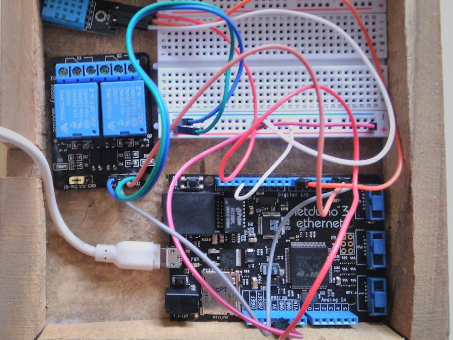
I have been working on this topic for quite a while(have a look at my previous projects). I am a huge fan of IoT and specially of home automation. These applications have the potential to bring out a great change in society and the standard of living. Guess what, I got to apply IoT through a new platform : C# Thanks to Wilderness Labs.
Let's get started!
1. Materials Required- Netduino 3 (Ethernet or WiFi)
- Relay module (I used a 2-channel relay in this project)
- Prototyping breadboard
- DHT11 for temperature Monitoring.
- Android device (to run the Xamarin App)
- Box (I used a wooden one)
Netduino is a development board that lets you code in C# to create IoT applications. It uses.NET Micro Framework. It is like an Arduino, with a lot of exciting additional features like -
- Connectivity using WiFi or Ethernet
- SD card support for additional persistent storage (up to 2GB).
- Much more.....
So, to use the Netduino, you will require Visual Studio 2015 which lets you create.NET Micro Framework Applications. (Please note that Visual Studio 2017 is still not supported)
https://visualstudio.microsoft.com/vs/older-downloads/
Go on and download the community version of VS 2015 from the link above.
Now, after you have installed this, follow the instructions listed on -
http://developer.wildernesslabs.co/Netduino/Getting_Started/
Setting up this device is somewhat difficult, so I would recommend you to join its community, which is very active and helpful. I have used the N3 Ethernet so I didn't require the Netduino deploy setup part. But it is easy to set it up, thanks to the software provided.
3. Wiring the ConnectionsNow that you have everything setup, go to the Netduino Samples repo and download the Blink program, then run it on your Netduino using VS2015 to ensure that everything is okay.
https://github.com/WildernessLabs/Netduino_Samples
Follow this video for more help.
After this, you're set to wire up the connections for our project. Follow the image below for the connections.
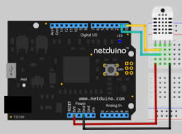
Have a look at the Fritzing connections.
Connection of DHT11 is very easy.
3.3V - VCC of the Sensor
Gnd - Gnd of the Sensor
Digital pin 2 - Output pin of the Sensor
After this is done, You are ready to go and code for your project.
4. Coding Part of the NetduinoNow with your hardware wired and you are ready to code the Netduino. We will be using the files of Request Handler and MapleServer Generation, which are provided in the projects of Netduino Samples Git repo. It is very easy to add these files into your VS project. Moreover, for relay coding, we will be using the relay sample or the connected coffee maker sample of the Git repo. The link to my Git repo and the Netduino Samples Git repo is provided below.
Now, to configure the DHT11 sensor, first you would be needing the 4 terminal raw sensor as the library I am using will only run if all 4 pins are connected correctly to the board.
using System;
using Microsoft.SPOT;
using Microsoft.SPOT.Hardware;
namespace Glovebox.Netduino.Drivers {
   public class DHT11 : DhtSensor{
       //private OutputPort m_op;
       //private OneWire m_ow;
       private OneWireBus.Device m_dev;
       public DHT11(Cpu.Pin data1, Cpu.Pin data2):base(data1,data2,Port.ResistorMode.Disabled)
       {
        //   m_op = new OutputPort(pin, false);
       }
       public float ConvertAndReadTemperature() {
           var data = 0L;
           // if reset finds no devices, just return 0
           if (m_ow.TouchReset() == 0)
               return 0;
           // address the device
           m_ow.WriteByte(Command.MatchROM);
           WriteBytes(m_dev.Address);
           // tell the device to start temp conversion
           m_ow.WriteByte(Command.StartTemperatureConversion);
           // wait for as long as it takes to do the temp conversion,
           // data sheet says ~750ms
           while (m_ow.ReadByte() == 0)
               System.Threading.Util.Delay(1);
           // reset the bus
           m_ow.TouchReset();
           // address the device
           m_ow.WriteByte(Command.MatchROM);
           WriteBytes(m_dev.Address);
           // read the data from the sensor
           m_ow.WriteByte(Command.ReadScratchPad);
           // read the two bytes of data
           data = m_ow.ReadByte(); // LSB
           data |= (ushort)(m_ow.ReadByte() << 8); // MSB
           // reset the bus, we don't want more data than that
           m_ow.TouchReset();
           // returns C
           // F would be:  (float)((1.80 * (data / 16.00)) + 32.00);
           return (float)data / 16f;
       }
       public void StartConversion() {
           // if reset finds no devices, just return 0
           if (m_ow.TouchReset() == 0)
               return;
           // address the device
           m_ow.WriteByte(Command.MatchROM);
           WriteBytes(m_dev.Address);
           // tell the device to start temp conversion
           m_ow.WriteByte(Command.StartTemperatureConversion);
       }
       public float ReadTemperature() {
           var data = 0L;
           // reset the bus
           m_ow.TouchReset();
           // address the device
           m_ow.WriteByte(Command.MatchROM);
           WriteBytes(m_dev.Address);
           // read the data from the sensor
           m_ow.WriteByte(Command.ReadScratchPad);
           // read the two bytes of data
           data = m_ow.ReadByte(); // LSB
           data |= (ushort)(m_ow.ReadByte() << 8); // MSB
           // reset the bus, we don't want more data than that
           m_ow.TouchReset();
           // returns C
           // F would be:  (float)((1.80 * (data / 16.00)) + 32.00);
           return (float)data / 16f;
       }
       public static float ToFahrenheit(float tempC) {
           return (9f / 5f) * tempC + 32f;
       }
       private void WriteBytes(byte[] data) {
           for (var i = 0; i < data.Length; i++)
               m_ow.WriteByte(data[i]);
       }
       private static class Command {
           public const byte SearchROM = 0xF0;
           public const byte ReadROM = 0x33;
           public const byte MatchROM = 0x55;
           public const byte SkipROM = 0xCC;
           public const byte AlarmSearch = 0xEC;
           public const byte StartTemperatureConversion = 0x44;
           public const byte ReadScratchPad = 0xBE;
           public const byte WriteScratchPad = 0x4E;
           public const byte CopySratchPad = 0x48;
           public const byte RecallEEPROM = 0xB8;
           public const byte ReadPowerSupply = 0xB4;
       }
   }
}
This is the code of the library I am going to use. Just add this in your DHT11 display file, by the "using" command, then configure the D5 pin as out and print its status on the debug window. That's it!
Here's the relay code:
using System;
using Microsoft.SPOT;
using Microsoft.SPOT.Hardware;
using SecretLabs.NETMF.Hardware.Netduino;
using System.Threading;
namespace Relay
{
   public class Program
   {
       public static void Main()
       {
           // create an output port (a port that can be written to) and connect it to Digital Pin 2
           OutputPort relay = new OutputPort(Pins.GPIO_PIN_D2, false);
           OutputPort relay = new OutputPort(Pins.GPIO_PIN_D3, false);
           // run forever
           while (true)
           {
               relay.Write(true); // turn on the LED
               Thread.Sleep(500); // sleep for 1/2 second
               relay.Write(false); // turn off the relay
               Thread.Sleep(500); // sleep for 1/2 second
           }
       }
   }
}
Let's make the board smart by creating a Xamarin App to control it.
5. Xamarin App PartNow that we have these things ready, we are read to create a simple Xamarin app that shows the status of the switch (on or off) and has 2 buttons to change the status of switches from off to on.
Here are 2 code snippets to help you understand more about the above feature.
Get Status Code Snippet:
public async Task<bool> GetLightSwitchStatus()
{
    using (var s = new Sockets.Plugin.TcpSocketClient())
    {
        await s.ConnectAsync(NetduinoIp, Port);
        byte[] data = new byte[2];
        data[0] = ReadLightSwitchState;
        data[1] = ReadLightSwitchState;
        s.WriteStream.Write(data, 0, 2);
        s.ReadStream.Read(data, 0, 1);
        return data[0] == ByteTrue;
    }
}
The above piece of code request the switch status from the server and returns true or false, depending on the status of the light switch.
Set Status Code Snippet:
public async Task SetLightSwitchStatus(bool on)
{
    using (var s = new Sockets.Plugin.TcpSocketClient())
    {
        await s.ConnectAsync(NetduinoIp, Port);
        byte[] data = new byte[2];
        data[0] = WriteLightSwitchState;
        data[1] = (byte)(on ? ByteTrue : ByteFalse);
        s.WriteStream.Write(data, 0, 2);
    }
}
This piece of code sends a request to the server telling which state the light switch should be set to.
Note how all the exchange of information is done via bytes, the first byte tells the server which operation is requested while the second one contains data when necessary.
I have used the tutorial by cssharpguy to create my simple app. Here's the video tutorial.
I have followed the connected CoffeeMaker Tutorial and used the same app for the project.
Now that it's all done, the project is ready to run. Here is the video tutorial showing the working of the project.
The video is of one of my previous projects, but the working principle is same. I couldn't get the Netduino tutorial video as I am currently facing some problems with my Netduino Board, will be updating the video as soon as my board gets working.
Thank you all for reading this project. Please respect and share it with your friends. :-)


Comments
Please log in or sign up to comment.