


Hardware components | ||||||
_ztBMuBhMHo.jpg?auto=compress%2Cformat&w=48&h=48&fit=fill&bg=ffffff) |
| × | 1 | |||
 |
| × | 1 | |||
 |
| × | 1 | |||
Hand tools and fabrication machines | ||||||
| ||||||
This tutorial explains how to set up a timer based interrupt. Specifically, it uses a timer compare interrupt to flash an LED at a regular interval, contrasting to the popular Blink sketch's use of delay(). Programming is specific to the 16MHz ATmega328P used in Arduino Uno, the 5V Nano 3.x, and clones.
My MotivationI have this crazy idea of building a three-unit Raspberry Pi cluster and using a custom 8MHz, 3.3V ATMega328P (the same chip as the Arduino Uno, but at lower speed and voltage) to switch between the Raspberry Pi console ports while also doing other useful things like measuring temperature and power supply status. My first step was to figure out the console port thing and that involved the SoftwareSerial library.
I have a 5V Arduino Uno and the Raspberry Pi is, of course, 3.3V. So rather than risk burning out my Pi, I cut a piece of wire to connect the software serial transmit and receive pins together, creating a loopback. The theory was sound, whatever I sent out on the transmit pin should come back on the receive pin. But, it didn't work. And it didn't work because of interrupts.
Interrupts are required for knowing when serial data is coming in on a particular pin, but, because of the critical timing, interrupts are disabled when transmitting. This arrangement makes it impossible to send and receive at the same time. Needless to say, this does not bode well for my idea of attaching to multiple Raspberry Pi console ports.
But, on the bright side, it got me interested in interrupts on the Arduino Uno.
Start SmallThe blink sketch. It's probably everyone's first Arduino project. Well, here it is again as a refresher.
#define LED 9
void setup() {
 pinMode(LED, OUTPUT);
}
void loop() {
 digitalWrite(LED, LOW);
 delay(500);
 digitalWrite(LED, HIGH);
 delay(500);
}
Note the familiar delay() subroutine to control the on and off timing. With 500mS in each state, the LED will pulse at a steady 1Hz.
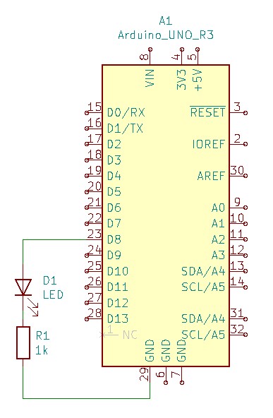
In my sketch, I'm using pin 9 for the LED. This requires attaching an LED and current limiting resistor between pin 9 and ground. I'm going to go out on a limb and guess that if you're reading a tutorial about timer interrupts, you've attached a few LEDs, and I'm not going to go into detail. It is important to use an external LED though, because later on, the built-in LED will be used simultaneously to compare interrupt blinking with delay() blinking.
If all you want to do is ooh and ahh over a flashing light, this sketch is perfect as it is. But, what if you wanted to do something else at the same time? Maybe measure the voltage across a thermistor and calculate temperature. That would be nice.
The problem is those two delay() function calls. Half a second is spent in each one doing absolutely nothing. You could insert the code before or after one of the delays. But what if that code takes long enough to execute that it throws off the timing of the blink?
You could shorten the delay. Maybe make it 490 instead of 500. Maybe that's too short and 495 is a better choice. At some point you'll probably throw up your hands and say, 'There's got to be a better way!'
There is a better way. It's called a timer interrupt.
What's an Interrupt?Take a look at the illustration from this tutorial's title card.
The dandy in the top hat -- he's an interrupt. You can almost imagine him hanging around an old Victorian train station saying something like, "Pardon me, my good sirs."
Now the three gentlemen on the bench -- they're the processes in your loop() function. The one on the left, sitting down, he's the LED when it's off. The next guy is the LED when it's on. And the third guy, the one with his hat over his eyes, he's got to be the delay function.
"Pardon me, my good sirs, " says the interrupt. Suddenly, he has the attention of the three men on the bench. Even the sleepy guy has pricked up an ear. It doesn't matter what they were doing before, they all stop and let the top hat wearing dandy take the stage.
This is exactly what an interrupt does. It stops the normal execution of your loop() and runs its own code for a while.
Brevity is Important
If top hat guy is a decent chap, he will keep his interruption brief. He might say something important like, 'Your train is about to depart, old sport, ' and then be on his way. Or he might hang around pontificating on the finer points of the latest trends in Ponzi schemes for hours on end.
The former is an example of a good interrupt, the latter is a bad interrupt. When an interrupt take too much time, it makes all the other processes wait. Interrupts should do only what is absolutely necessary and relinquish control back to the main loop.
In the case of a flashing LED, that bare minimum of processing comes down to changing the state of an output pin so the attached LED either turns on or turns off. So before we go any further, take a gander at the following line of code:
PORTB ^= B00100000; // Toggle bit 5, which maps to pin13.
What does it do? Well, reading the comment, it says it toggles a bit that maps to a pin. The pin happens to be pin 13, which is the built-in LED on the Arduino Uno. PORTB is the register controlling pins 8 through 13 on the Uno. Bit 0 controls pin 8, bit 1 is pin 9, and so on. Bit 5 controls pin 13, the built-in LED.
The ^= operator is an exclusive-or (XOR.) XOR can be used to invert any bit where one of the operands is a 1. XOR is like a regular OR with a twist. Two zero bits as input give a zero as output. A zero and a one or a one and a zero give an output of one. But, and here's the twist...if you have a one and a one, the result is a zero.
That's why the line of code above will flip only the bits where the one is. If the current value of bit 5 of register PORTB is zero, that zero XOR'd with the one in bit 5 of binary value B00100000 results in one. If bit 5 of PORTB is a one, one XOR'd with one gives zero. The bit flips every time the XOR is applied. Any other bits in PORTB will XOR with zero, resulting in the original value being returned and leaving them unaffected.
What would have been an exercise in determining the pin's current state with a digitalRead() and then applying the opposite state with a digitalWrite() is now done in a single XOR. Quick and efficient, just like any fine, upstanding interrupt should be.
I'm Sold, Where Do I Get One?With the basics out of the way, it's time to get down to the business of setting up the interrupt. This involves two parts.
The first is the interrupt service routine (ISR). It's just a subroutine to execute the bit flipping code. The ISR() subroutine exists outside of the setup() and loop() routines, and it looks like this:
ISR(TIMER1_COMPA_vect)
{
  PORTB ^= B00100000;  // Toggle bit 5, which maps to pin13.
}
In its simplest form, ISR() takes a single argument. That argument, TIMER1_COMPA_vect, is the vector (or source) of the interrupt. With a name like TIMER1_COMPA_vect, you can probably guess it has something to do with timer1 and maybe there's some comparing going on. You would be correct.
But we're not done. All we've done so far is tell the ATmega328P what to do when a timer compare interrupt occurs. We haven't actually set up any timers to generate an interrupt, so nothing will happen yet.
The second part of setting this up involves telling the timer when to raise an interrupt. That involves more control registers and binary values, but if you've made it this far, you'll be fine. Here's the code:
cli();
TCCR1A = B00000000;
TCCR1B = B00001100;
TIMSK1 = B00000010;
OCR1A = 31250;
sei();
The cli() and sei() instructions are related. The first clears the interrupt flag and the second sets it. The interrupt flag is what allows interrupts to occur. Using cli() ignores all interrupts, essentially it's a big do not disturb sign. sei() does the opposite and allows interrupts.
The reason to initially block interrupts with cli() is because there are four registers that need to be set up and all four are related. Getting only one or two set up before interrupts start rolling in will result in some unpredictable behavior. Better to put out the do not disturb sign while the setup is happening.
The registers (TCCR1A, TCCR1B, and TIMSK1) are a collection of flags dictating how timer1 functions. In the code, all are set using binary values to make it easier to see which bit is being set and if it's with a one or zero.
OCR1A is the value to compare with the timer's current count. It's shown in decimal notation to make it easier to read. As it's configured, the timer will start from 0 and count up. When it reaches the value stored in OCR1A, something will happen. If you guessed that something is an interrupt, you win a prize.
How fast the timer counts and what it does when it reaches the value in OCR1A are dictated by the flags in TCCR1A and TCCR1B. These timer control registers are detailed in section 15.1 of the ATmega328P data sheet. But here is a brief description:
TCCR1A = B00000000is the simplest. It sets up all zeros, or what's referred to as "normal" mode.
TCCR1B = B00001100dictates how fast the counter counts with the values of bits 0..2. In this case, binary 100 in those lower bits sets the prescaler to 256 (more on that later.)
- Also included in
TCCR1B = B00001100, a one in bit 3 means the counter will reset to zero when the value stored in OCR1A is reached.
TIMSK1 = B00000010ensures the interrupt will be generated when the counter reaches the value stored in OCR1A.
The last register being set up is OCR1A, the compare register, but why is it set to 31250? The answer to that lies in the following equation:
interrupts_per_second = clock_speed / prescaler / OCR1A
It can also be expressed as
OCR1A = clock_speed / prescaler / interrupts_per_second
With a 16MHz Arduino Uno and a prescaler value of 256 (remember the lowest 3 bits of TCCRB1 set this value) the equation becomes simpler:
OCR1A = 16MHz / 256 / interrupts_per_second
OCR1A = 62500 / interrupts_per_second
I want to toggle the LED twice per second to get a 1Hz blink rate, so I divide 62500 by 2 to get 31250. That's where the OCR1A value comes from.
Let's Blink!So far, it all been a bunch of theory. Let's put all the code in a sketch and prove that it actually works. Here's what it looks like:
#define LED 9
void setup() {
 pinMode(LED_BUILTIN, OUTPUT);
 pinMode(LED, OUTPUT);
 cli();
 TCCR1A = B00000000;
 TCCR1B = B00001100;
 TIMSK1 = B00000010;
 OCR1A = 31250;
 sei();
}
void loop() {
 digitalWrite(LED, LOW);
 delay(500);
 digitalWrite(LED, HIGH);
 delay(500);
}
ISR(TIMER1_COMPA_vect)
{
 PORTB ^= B00100000;
}
Notice how the old way of delay() blinking is still included, but now the new interrupt code part of the sketch, too. This is the reason for using two LEDs. The external LED (pin 9) will be controlled by the digitalWrite()s and delay()s inside the loop() while the built-in LED (pin 13) is controlled by the ISR() and the configuration inside setup().
Load the sketch to an Uno and you should see the two LEDs blinking in unison.
Now, make some changes. Try any or all of the following:
- Double the value of OCR1A and make it 62500.
- Set the prescaler bits for a value of 64 instead of 256. (TCCR1B = B00001101)
- Change both delay() values to 250 instead of 500.
- Delete everything inside loop().
Make a prediction about what will happen in each case and upload the sketch to see if you're right. While you're thinking, imagine what the effect would be of an Arduino Uno with an 8MHz clock crystal in place of the standard 16MHz.
As a final exercise, and this one will take some time, leave the original sketch running for several hours or even overnight to see the effect on the LED synchronization. (Spoiler: they're going to be noticeably out of sync.) Come up with some theories on why that would happen. Which LED's timing is more accurate?
Next StepsBlinking LEDs is fun for a start, but interrupts can be used for much more. For example, there are interrupts that can be triggered by changes on input pins. Now that you know how to write an interrupt service routine for toggling an LED on or off, try triggering it with a a button assigned to an input pin instead of the timer.
Being an introduction, this tutorial shows only one way to configure interrupts on an ATmega328p. There are also higher-level functions like: attachInterrupt() and detachInterrupt that cover a broader range of Arduino models and take care of the details so you don't necessarily need to read data sheets and set bits on registers.
Wherever you plan to take your new knowledge, knowing how interrupts work will allow you to build better and more efficient sketches. So, ditch the delay() and start using more interrupts.


Comments
Please log in or sign up to comment.