The Linkit Duo contest theme revolved around smart homes. I though a bit about it and immediately I knew that this was the perfect board for a project I had thought about for quite a while. Bringing IOT to gardens by using perpetual wireless sensor nodes. What do I mean by perpetual? Read on to find out.
So, I decided to build a project that would monitor garden temperature , humidity and dew point. Monitoring your garden is quite valuable if you want to gain insight on how the plants deal with changes in weather. Rather than measure this manually why not automate the whole procedure by installing wireless sensors.
The idea is quite simple. Deploy a small network of wireless sensor nodes which can transmit sensor data wirelessly to a central hub represented by Linkit Smart DUO. A web app running on the Linkit platform parses and visualizes the received serial data. At present the proof of concept prototype is not connected to any online services. When I want to check the temperature and humidity state from the garden i simply open a web-page from within my home network. The data is stored on a the USB flash since most database frameworks are really memory heavy for the Linkit board.
The project is composed of four parts.
- Designing the motes (wireless nodes) including both hardware and firmware.
- Designing the communication hardware for the hub side. This was a breakout board for the radio module I used.
- Writing the Arduino firmware for the Linkit Atmega32 MCU.
- And finally designing the web app that would parse the serial data from the MCU.
This shaped up to be a long journey of caffeine fueled troubleshooting afternoons so make a cup of tea to hear the whole story.
HardwareThe hardware for the motes and the hub was one of the main components of the project.
Hub designThe Linkit Duo is used as a sensor hub. The addition of a WIFI board makes for a very compact base-station. Initially I thought about using the ESP8266 modules. But then after some back of the envelope calculations I realized WIFI is a power-hog so I decided to use a low power radio to communicate with the motes. After some pondering I settled on the RFM69CW since it offers the best balance between range and power consumption. The hardware on the Linkit side consist of a single breakout board with an ISM radio operating at 915MHZ.
This can be legally used in North America in the ISM license free band. The radio communicates with ATMEGA MCU via the SPI bus. The radio reset pin is connected to pin D5. The interrupt pins are connected but not used the present firmware version.
The radio is fed from the 3V3 power pins of the Linkit board. The SPI peripheral pinout can be found on the Linkit manual.
After thinking about the wireless nodes (motes) for a while it dawned on me that changing the batteries on the mote is a major hassle. So I decided to add solar harvesting capability to the wireless sensor nodes. A lipo battery was used.
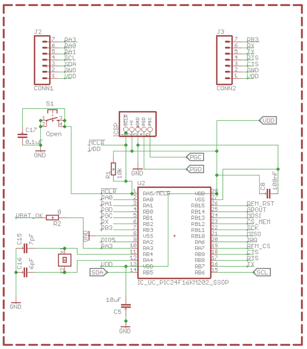
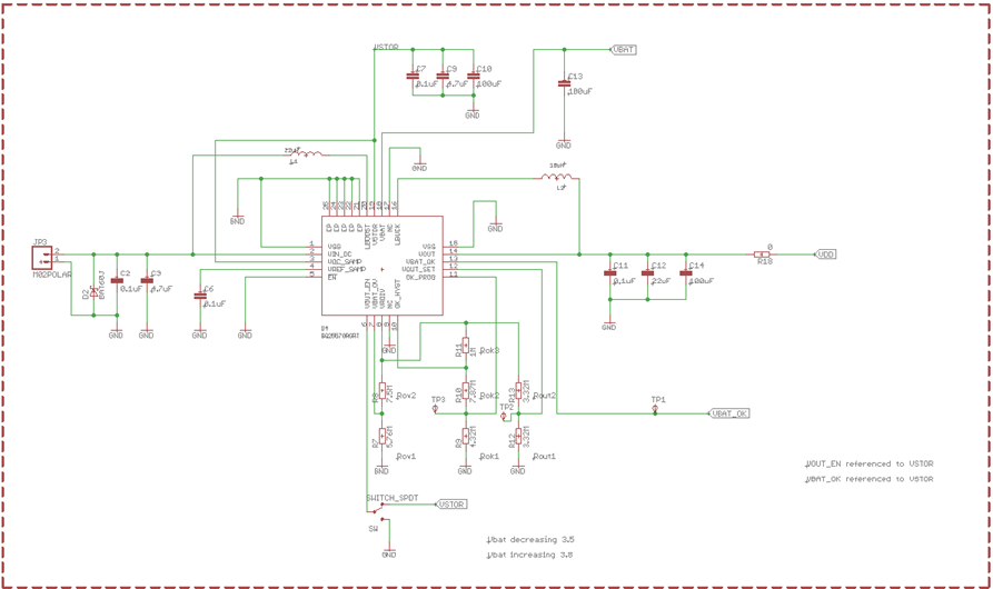
The majority of the time went into the mote design. The mote uses a low power PIC24F16KA102 MCU, the same radio module and a BQ274110 fuel gauge to measure battery state. The main choice that sets it apart from other motes on the market is the inclusion of a low power energy harvesting chipset. The BQ25570 chipset from TI is quite expensive (~$10) in single quantities but it is also quite efficient. The buck can start harvesting energy from as low as 365 mV. When the voltage from the solar panel increases above 0.5 V the buck can boost it to the programmable output voltage. Initially I set the output voltage to 3V. Later I found that I can set the output voltage to as low as 2V. Yeah, operating a wireless sensor node from as low as 2V. Depending on the duty cycle of sensor sampling the node may last up to 6-7 years with a single battery. Pretty close to being perpetual for all intents and purposes.
The photo below shows the designed mote. As you can see the headers have a prescribed layout. That is not by chance. I designed it such so that the user can plug and play with various I2C sensors as shown in the figure below.
After receiving the PCB from the fab house I populated the boards and started writing firmware to test all the peripherals. I built two motes initially. The solar panels have an output voltage of 3.3V and a current output of 100mA .
MeasurementsTo verify proper operation i took a bunch of measurements. I used an Analog Discovery multi-function tool. The best thing about it is that it has a programmable voltage supply that can be tuned from the program with as little as 1mV resolution. Who need knobs anymore?
The programmable voltage supply was connected in place of the solar panel. And the voltage was swept though various values. As you can see the moment where the mote power supply triggers is around 365mV. The output value has a high ripple and is at 1.5V. When the voltage increases above 550mV then we find ourselves in business.
For the next test I removed the solar panel and powered it only from the battery. It worked. The last tested was plugging both battery and solar panel. After verifying that the board worked I started work on the firmware.
Hub FirmwareThe ATMEGA 32UA MCU on the Linkit board is an excellent choice that augments the capabilities of the board. Using the Arduino framework sped up the development of this part significantly. From te documentation I found that the Atmega uses the default Serial port for programming and Serial1. port for communicating with the Mediatek MPU.
After connecting the radio to the MCU I wrote a program which would dump all the radio registers. Success!
The next step was writing a program which would output the received serial data to the MPU serial port. The MPU serial port uses a default baud rate of 56000.
Aftre turning on the node I could see the streaming data. The current firmware contains no sensor code so I am sending a Hello string.
The fourth packet byte is used as a counter which continuously increments by 1. Pressing the reset button on the board during transmission resets the counter.
The incoming data was printed on the normal serial port and then also sent to the Linkit Hub via Serial port 1. The data is then consumed by the app running on the MPU.
Mote FirmwareThe mote firmware is composed of the same radio librray and the flash memory driver at present.The mote firmware simply transmits a fixed string with the words Hello Mote 1 or 2 and it also has a counter which increments as pointed above.
Optimizing and adding features to the mote firmware is on the TODO list. The attached code at the end of the article includes the hub ATMEGA32 code and the radio driver. I used an external library for the RFM69CW radio. The same code library is used on the motes. The code below shows the transmitter code on the mote
   while(1)
   {
       rfm69_send(testdata, sizeof(testdata));
       rfm69_sleep();
       testdata[1]++;
       testdata[2] = rand()*10;
       xprintf("Message sent\n");
       __delay_ms(2000);
   }
If somebody wants to replicate the project for the motes one can use Arduino compatible motes from Low Power lab without the energy harvesting feature obviously.
SoftwareWorking on a multifaceted project such as this has its challenges. The Hub software presented some of these. Initially I wanted to simply code a NodeJs app. With version 0.9.4 of the firmware I found that the node serial port had been removed. Probably because the Firmata library also contains the same library. I was not aware of that at the time. It comes out that one can install the node serial port if compiling the module from source.
The other challenge was that Linkit has only 32MB of storage. So storing data on the flash memory is out of the question. For the prototyping stage I just wanted to verify the functionality of the app however.
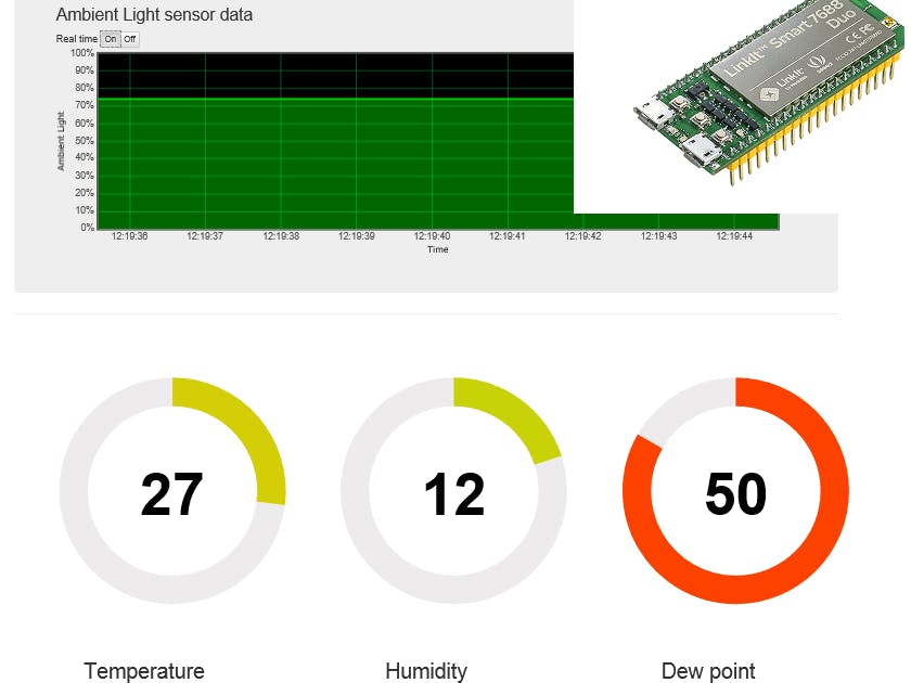
I then coded a small node serialport app which dumped all the data from the MCU to the terminal as shown on the image above. Then I shifted gears and selected Python Flask. I designed a dashboard that contains a graph and three gauges . Each of the gauges would show the temperature , humidity and dew point on the garden. The data read from the serial port which is polled continuously are visualized using the Flot javascript library.
The dashboard was coded just to prove the functionality of the project and needs more features.
Features to be included in future work are integration with Mediatek cloud, optimizing firmware as well as designing a shield for Linkit board.
FinThis project presented the design of a dashboard ecosytem focused on monitoring garden environmental sensors. The energy harvesting wireless senor mote and the Linkit WIFI enabled board make an excellent combination for connectivity projects.
A lot of thanks to Mediatek and Seed studio for the nice Linkit board. It took a lot of work but I am glad to say that the connected home is within the reach of everybody.
Hope you enjoyed it.


Comments
Please log in or sign up to comment.