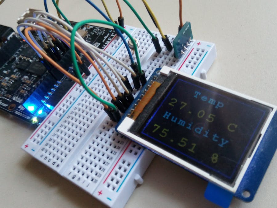
Let's build a temperature and humidity monitoring solution with a Zynq FPGA SoC. This project will use the MiniZed development board. Take a look at the previous tutorial for getting started with the MiniZed board.
This assumes that you are comfortable with the basics. Here, we are going to use the PL section of the SoC to interface an I2C temperature and humidity sensor and a 1.8-inch display based on the ST7735 TFT controller.
The PS section of the SoC will be used to implement the state machine that queries both the sensor and updates the display.
Building the HardwareI used the free version of Vivado 2017.4 to implement the Zynq hardware. The first step is to add an instance of the Zynq SoC. Then double click on it and configure the AXI master mode in order to connect the PL peripherals via the AXI bus. The Master AXI GPO interface allows connecting the various peripherals to the PS (ARM ) part of the SOC.
To build the hardware on the PL section we are going to use three standard PL periplerals; AXI SPI, AXI GPIO and AXI IIC. The complete memory map of all the peripehrals used is shown below.
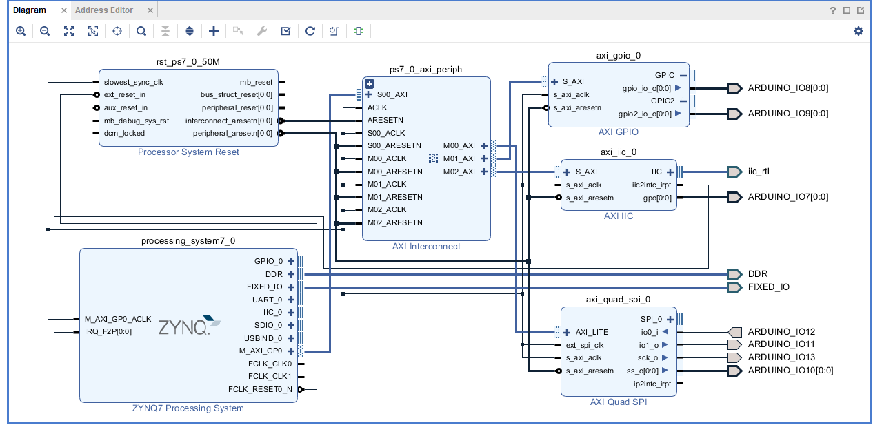
The AXI SPI is used to interface with the display. The SPI core is configured in Standard mode meaning you have the usual SPI bus output. Since the TFT display has some additional control and data signals apart from the SPI bus an AXI GPIO was used.This was configured to have two output buses of width 1. The GPIO interface was set to custom since the board definition does not include this specific interface.
In addition, an AXI IIC core will be used to interface with the humidity sensor. The I2C operates at 100Khz.The next step is to import the constraint file and select the pins. To maintain compatibility with Arduino board I used the same pinout that is on an Arduino shield.
The schematics of the main system is shown below.
I have exported the hardware as an HDF file so that you don't have to build it from scratch.
After the bitstream is exported, the next step is to launch the SDK from the File - launch SDK command. Then we code the program residing on the PS that will tie all the hardware together. The PS is actually a single core ARM Cortex A9 running at 666 MHz.
Since we are not using Petalinux in this case the on-board switch is moved to JTAG to allow programming of the board via the FTDI JTAG bridge.
PS FirmwareThe firmware is implemented on the PS section of the SoC using the Xilinx SDK. The firmware uses the BSP for the exported hardware to build the low level drivers for interfacing with the external devices. A graphical stack library was implemented for the TFT display.The driver for the Si7021 was adopted from the Avnet code for the HTUD21 since both sensors are pretty much identical.
A standalone BSP package was used. The other option is to use a BSP with FreeRTOS.
Click on the BSP and modify the settings so that stdout and stdin are piped to UART1 of the PS. This is by default set to 115200 8N1.
Demo Time!That's it. This project showed how to use all the most common peripherals on the Zynq SoC. In addition we build a small temperature and humidity monitoring solution that uses the PL section of the FPGA.
Future augmentation may add sound monitoring capability by adding an I2S core for the microphone.


_3u05Tpwasz.png?auto=compress%2Cformat&w=40&h=40&fit=fillmax&bg=fff&dpr=2)

Comments
Please log in or sign up to comment.