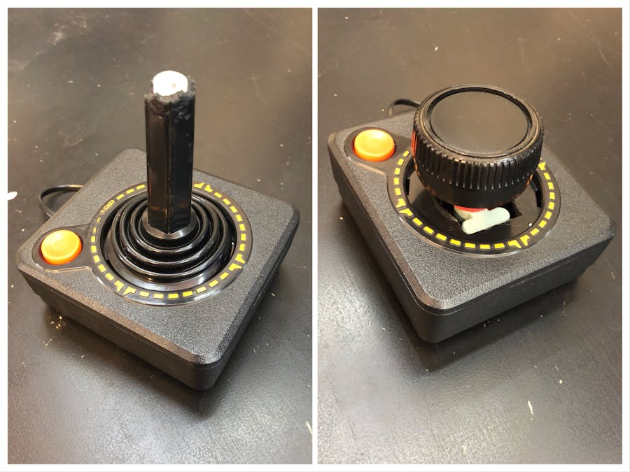
This is my entry for Infineon's Sensing the World in All Three Dimensions Contest. My idea was to make a modern repalcement for retro Atari controllers that doubles as an Atari joystick or an Atari paddle. A joystick controller has 4 directions and a button. The paddles are meant to be rotated and also have a button. I'm a big fan of retro games and saw that Infineon makes two add-ons for the 3D 2GO kit that were perfect for my idea.
My project fits inside the enclosure from the original Atari Joystick. I noticed while salvaging parts for this project that the buttons that are used to detect direction on the Joysticks often wear out. I only had one out of three controllers that was perfectly usable. In the same vein, the potentiometer on the Paddles often wear out and cause janky movement. I'm using a single magnetic sensor to replace the elecro-mechanical sensors that were used for rotation and direction in the two original controllers. There is a single firmware image that switches between Joystick and Paddle mode by pressing the button at startup.
ElectricalI'm using the Infineon 3D Magnetic Sensor 2Go TLE493D-W2B6 evaluation board for the brains of this project. It has an XMC1100 ARM M0 microcontroller with onboard debugger and TLE493D 3D magnetic sensor onboard. I soldered headers to this evaluation board to make future connections easier. Unfortunately this evaluation board does not have a connection point for the USB 5V link, so I attempted to solder to the traces. This was a mistake because I ripped the trace off and couldn't fix it. I had to order a new evaluation board to finish the project. To get around this requirement, I spliced a USB power cable into the 5V line from the Atari. Now the evaluation board receives 5V from USB and provides 3.3V to the MCU and other circuitry on the board.
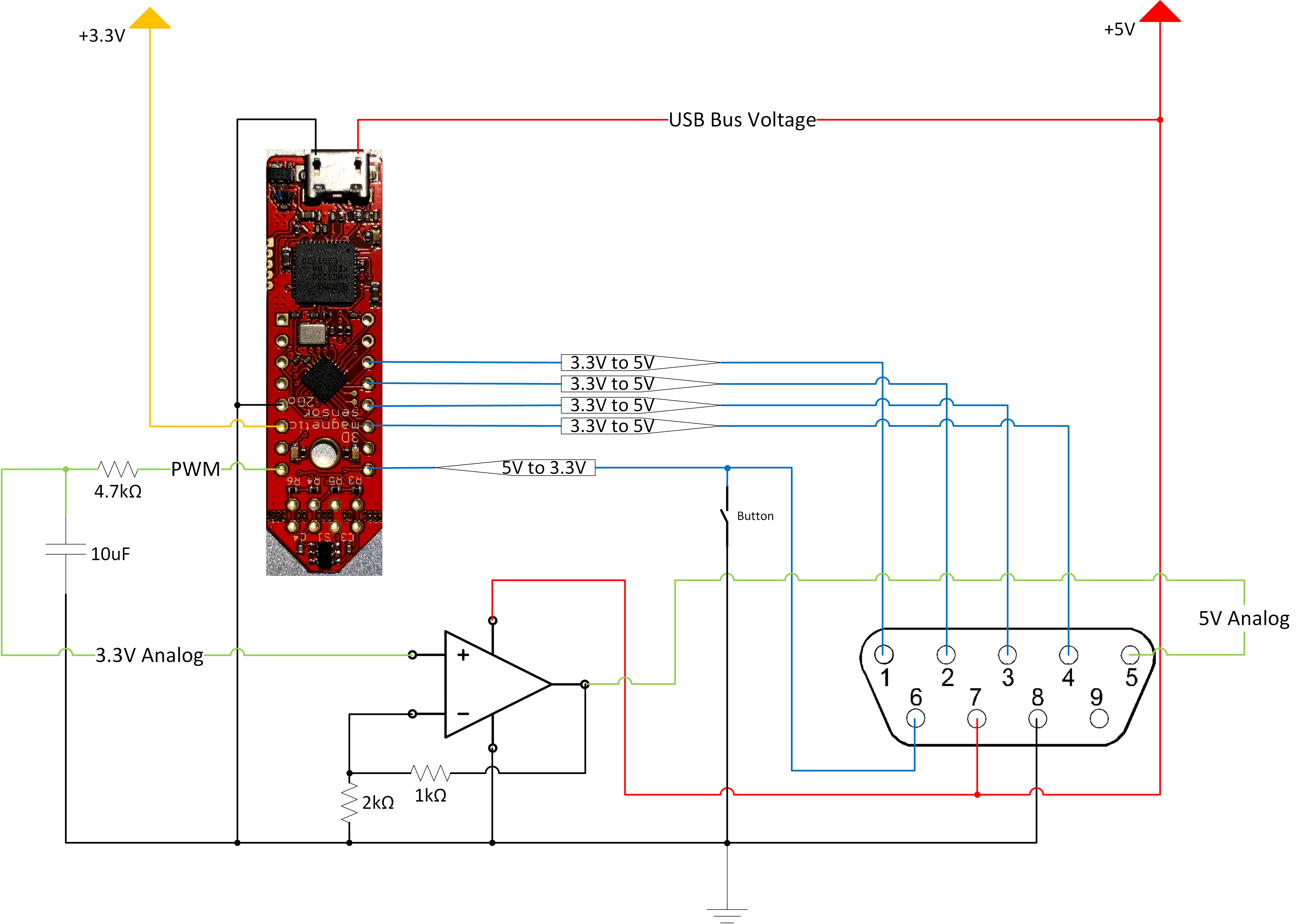
The above connection diagram is also on Google Docs. It explains the MCU's pinout and what the pins are named in the Arduino IDE. The connection columns show where that pin goes and where it eventually connects on the BD-9 cable after the voltage translation. All of the signals to and from the Atari are normally pulled high and set when pulled low. Note this is from the bottom of the eval board so it appears mirrored compared to the above photo.
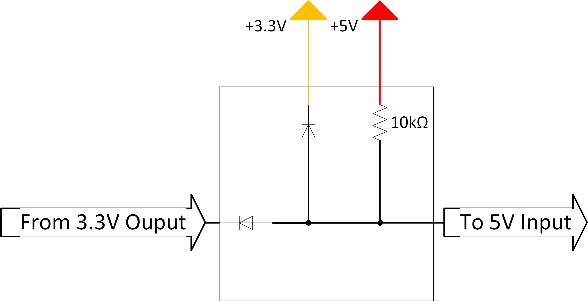
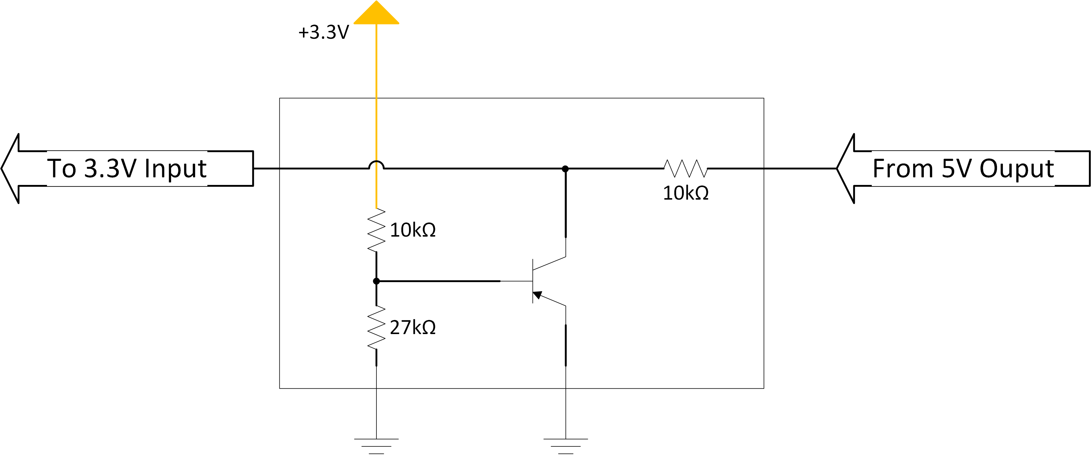
The microcontroller runs at 3.3V and the Atari's IO levels are at 5V so voltage translation is required. I initially tried to use a TXS0108E IC for level shifting, but it didn't work. I think the issues were a combination of wires that were too long and the bidirectional circuit didn't like only sending data in one direction. Someone on Twitter pointed out this excellent document by Microchip about translating between voltages. It was super helpful and I used a few circuits from it to fix my problems. I used Tip #7 for translating the 3.3V direction outputs from the MCU to the 5V inputs for the Atari. I used Tip #11 for translating the 5V mechanical button state to 3.3V for the MCU. I biased the transistor's base a little lower with a voltage divider to get exactly 3.3V to the MCU. Both of these schematics are shown above. I also used a similar circuit as #14 to translate the 3.3V PWM output of the MCU to an 0-5V analog voltage on the Atari.
The 3.3V PWM goes through an RC filter to convert to 0-3.3V analog. Then that signal goes through a rail to rail op amp with a gain of 1.5 to convert to 0-5V analog. I used a TSV91x because that's what I had available in my parts bin. A rail to rail op amp is important here because the Atari expects the signal to be 0-5V and there isn't a higher voltage rail available to reduce our losses.
The last piece of the electrical system is a female DB-9 connector and a straight through male DB-9 to female DB-9 cable. Both of these items are easy to find and relatively cheap.
CodeFor this project, I wrote all of the code using the Arduino IDE. You can install the board in Arduino using the readme’s instructions at this GitHub: https://github.com/Infineon/XMC-for-Arduino In Arduino, the board is called "XMC1100 XMC2Go". You'll also need to install the library for the magnetic sensor from this GitHub: https://github.com/Infineon/TLE493D-W2B6-3DMagnetic-SensorInfineon also has a Windows GUI for visualizing the data from the magnetic sensor which was really helpful for me when I was getting started.
The code will be in the code section below. The top of the code sets up the pins and the sensor. The setup() section enables the sensor (and resets it because the library is buggy), then sets the pins to the correct direction and state. It then detects if the mechanical button is pressed or not. I use the state of the mechanical button at startup to set the mode of the controller. If it's not pressed, the controller is initialized as a Joystick. If it is pressed, it behaves like a Paddle controller.
Inside the loop(), it either acts like a Joystick or a Paddle depending on the previous check. In Paddle mode, we update the data and check the X and Y positions. I use this positions and calculate the arctangent to find the angle. This angle is differenced from the previously determined angle to determine the direction it is spinning. The duty cycle of the PWM is then reduced or increased to match the direction of rotation. Finally, the state of the button is set if either the mechanical button is pressed or the rotation knob is pressed down. The getNorm() function determines the Z distance of the knob so it is used to detect if it is far away (not pressed) or close (pressed). In Joystick mode, we also update the data to read the X and Y positions. The maximum reading in each direction (up, down, left, right) is known so a calculation is performed to determine which direction has the highest reading and thus the corresponding direction's output is set. There is a deadzone area in the center of the controller so when the joystick rests in the middle, no directions are set. There is no logic relating to the button in this state because the mechanical button is electrically connected to the Atari here.
MechanicalAs I mentioned earlier, I 'm using the case from the original Atari Joystick as the enclosure for this project. This requires modifying a few parts of it to make it fit. I cut off the center rotating point and the pillar under the old button and I had shave the old cable port too (each detailed in photos above). I also had to make room for the DB-9 connector and USB cable (having the USB cable external also is helpful for debugging the code). I also added two holes to push the magnet adapters out from the bottom and also had to modify the lid so there's room to push it. This old plastic is very brittle and the side cracked apart when I applied pressure. Be very careful when removing material or more than you like will break off.
I used Fusion 360 to design a model that will hold the evaluation board, the magnetic sensors, and the button. Fusion 360 has a feature where you can insert a "canvas", which is just an image and draw on top of it. I took a top down photo of the original Atari controller board and imported it into Fusion 360. Then I stretched the canvas so it measured the same as in the real world. I could use this canvas to lay out the model and I knew that the holes and other features would line up. I was seriously impressed by this feature. It certainly saved me a lot of time (although I did print 4 versions before I settled on the current model, but that's mostly because I added extra features). I used the canvas to place the magnetic sensor exactly in the center of the joystick. I did this so I wouldn't have to factor in an offset to my sensor readings. The evaluation board is held in just by a press fit. The two magnetic sensors (joystick and rotation) are meant to be installed onto the evaluation board. I decided to mirror them away from the eval board to make installation and removal easier and allow room for wiring. I mirrored them across the point where the magnets are so they are perfectly centered. There's slots that hold it very tightly. My model also has an extruded area to hold the button so that I can use the original button cover and have the same mechanics.
The second item I 3D-printed for this project is an adapter for the Paddle. I went through many variations of this part, and settled on this one (although I'm not completely happy with it). It's simply a cylinder that slips around the rotation magnet's knob with a hole in the center to fit the shaft. I used a D-shaft from a potentiometer I had in my parts bin (although I suppose you can use the original Atari potentiometer). I cut it to length and attached it by heating up the 3D-printed part and finally applying epoxy. It's the best design I made so far but it's still a little janky. I am thinking about printing a large ring around the lid to hold the Paddle and hide the internals.
UsageA couple tips to start about using an Atari 2600 in 2018. I bought an adapter on Amazon to convert the Atari's F type video cable to a RF coaxial connector. I also bought some ferrite beads to quiet the power and video lines (but my room has significant RF emissions, so this might not be necessary for everyone) and produce a clean video signal.


_t9PF3orMPd.png?auto=compress%2Cformat&w=40&h=40&fit=fillmax&bg=fff&dpr=2)


_3u05Tpwasz.png?auto=compress%2Cformat&w=40&h=40&fit=fillmax&bg=fff&dpr=2)

Comments
Please log in or sign up to comment.