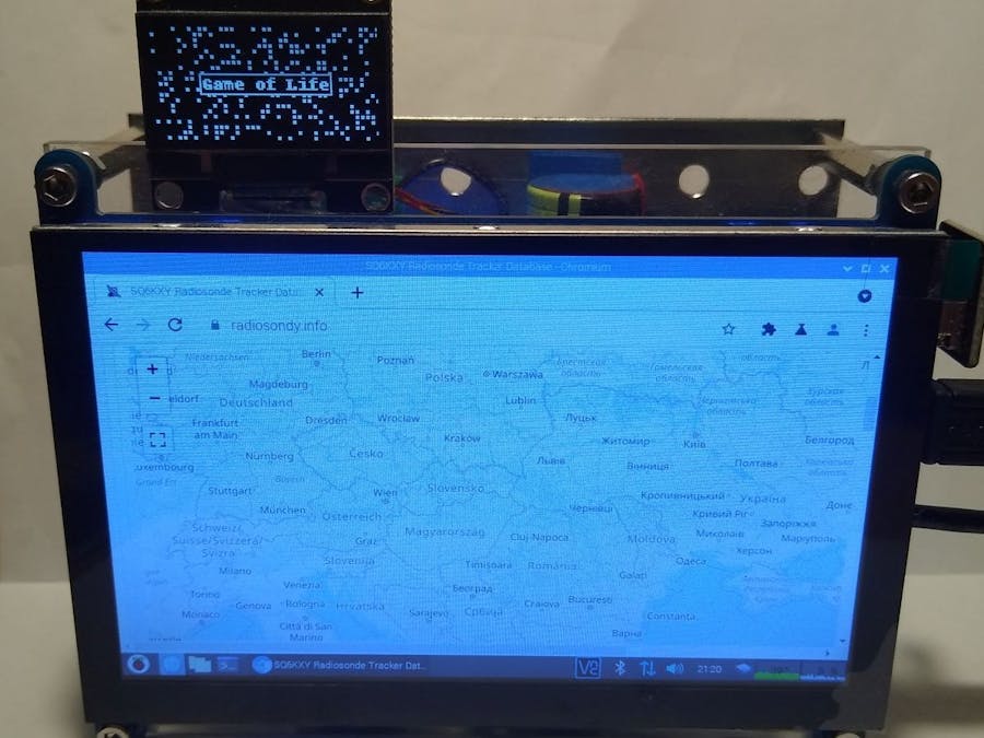
Disclaimer - this is a project showcase, not a how to, but you can get the idea.
I build this few years ago with the Pi 3 A+, but that version was always power hungry (hungrier), needed good power supply, was terribly slow and ofter had SD card corrupted due to power outages.
Due to pure luck I was able to buy Pi Zero Wireless version two (Pi0W2) at the day of release - I was very fond of first Pi Zero W, as it need very little power, has ability to mount external WiFi antenna (with some mod ofc.) and is easier to work with than ESP chips.
Version two has parametres almost same to Pi3A+ - that is quad core CPU, 512MB of Ram, I think it consumes less power and has faster WiFi. With a little cooler it is also little bit overclockable.
Everything fits around small LCD touch screen with 800x480 resolution, on which is mounted a custom CNC machined plastic frame, that has mounting holes for any RPI (thank god these fit all, so swap from one Pi to another is harmless). Touch is decent for price, and you can control Pi with at least some precision. So with that - on back of plastic frame a Pi0W2 is resting, with small heatsink for little overclock, that was tried out of pure fun, not that it helps or feels faster, but seems this Pi reacts much better when desktop is running (instead of older Pi3a+, that felt like snail).
For a connection a reduction from Mini HDMI to HDMI and a flexi HDMI - HDMI cable is used to connect Pi to LCD. For powering LCD, a Micro USB to USB OTG adapter with USB back to micro USB is used - I tried to find micro USB to micro USB cable, but with no luck. I only recently found site that offers custom flexi cables like one for HDMI - they are used for gimballs of drones, very thin and can be assembled to short lengths.
For power protection, a simple UPS was made. A USB-C Lithium charger is connected to 18650 battery (can be any Li-Po or Li-Ion, I chose this because it did not had protection circuit - that is on the charging board itself). In same time. output of charger connects to small boost circuit, capable to give 10W of power, that is 5V 2A (on paper). Plus output of this boost board is connected to one cathode of double Schottky Diode with common cathode (looks like big transistor on photo above). Other cathode is connected to plus source from the USB power itself - I have solder pad directly on charger board.
From the schottky Diode You get little less than 5V, but in my case it was 4.95V, Pi0W2 does not matter and I can live with that. Pi3 would be all over "insufficient power supply" warnings.
Everything has common ground. Also, from 5V a small fan is blowing on CPU heatsink. Everything power related is mounted on mounting iron plate, since I do not have CNC or 3D print capabilities anymore. Plate does lower the Wifi Signal, but those joke of antennas on Pi are weak anyways and thing is near Access point, so there is not much problem with it.
For a small stats, like time, IP, CPU temp, RAM usage etc. a small SSD1306 display is used - currently running Game of Life on it :) You can easily control it with Luma.Oled library for python straight from Pi.
I use this as a viewer of Dakboard or Radiosondy weather ballons page. Also its a good thing to have such small project to learn with it.
Plans for the future -
-put a schematic of it here
- put a voltage comparator or ADC for safe shutdown of Pi if battery voltage reaches critical level (around 3V). Comparator is easier to set and can work with other hardware as well, but ADC can monitor exact battery charge / discharge over time.
- buy a U.FL connector and modify Pi for usage with external WiFi antenna.
- control CPU fan with PWM from Pi, since it is little on the louder side.
- since this is resting on window still, a pi camera installation is planned to take outside pictures as seasons change, but i need a working python library for that (currently there is none for Bullseye version of RPi OS - yes, that is the latest one.)


Comments
Please log in or sign up to comment.