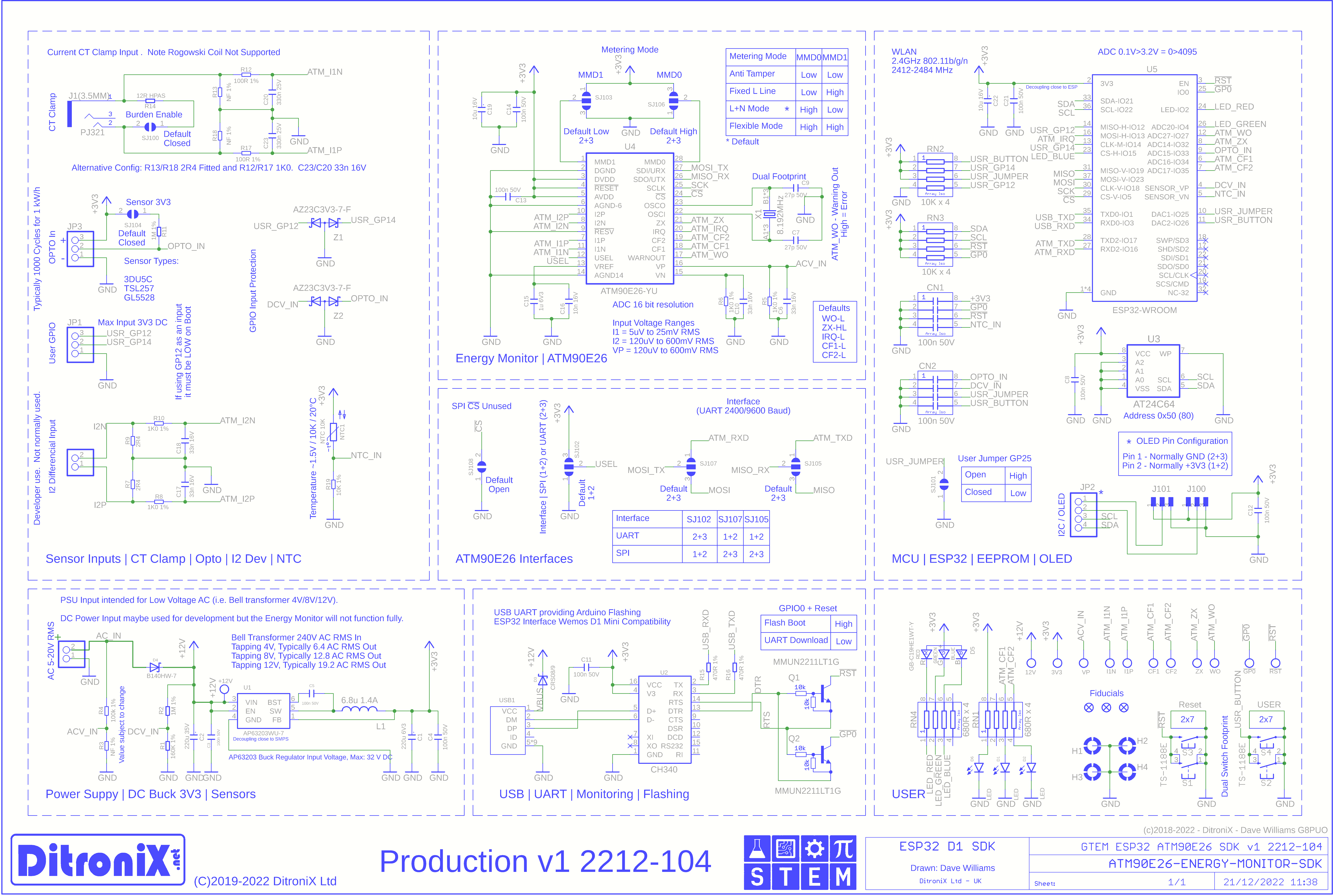
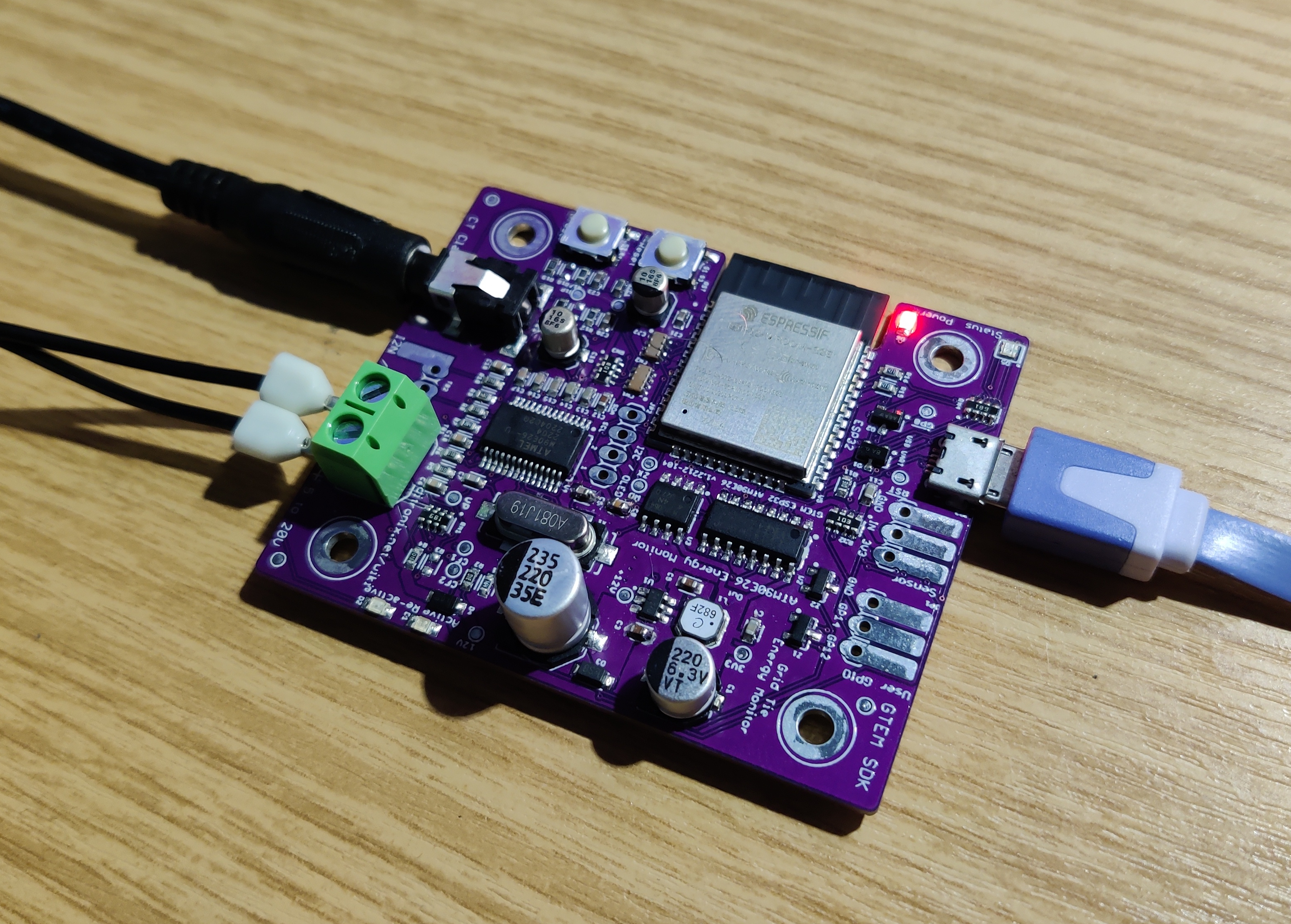
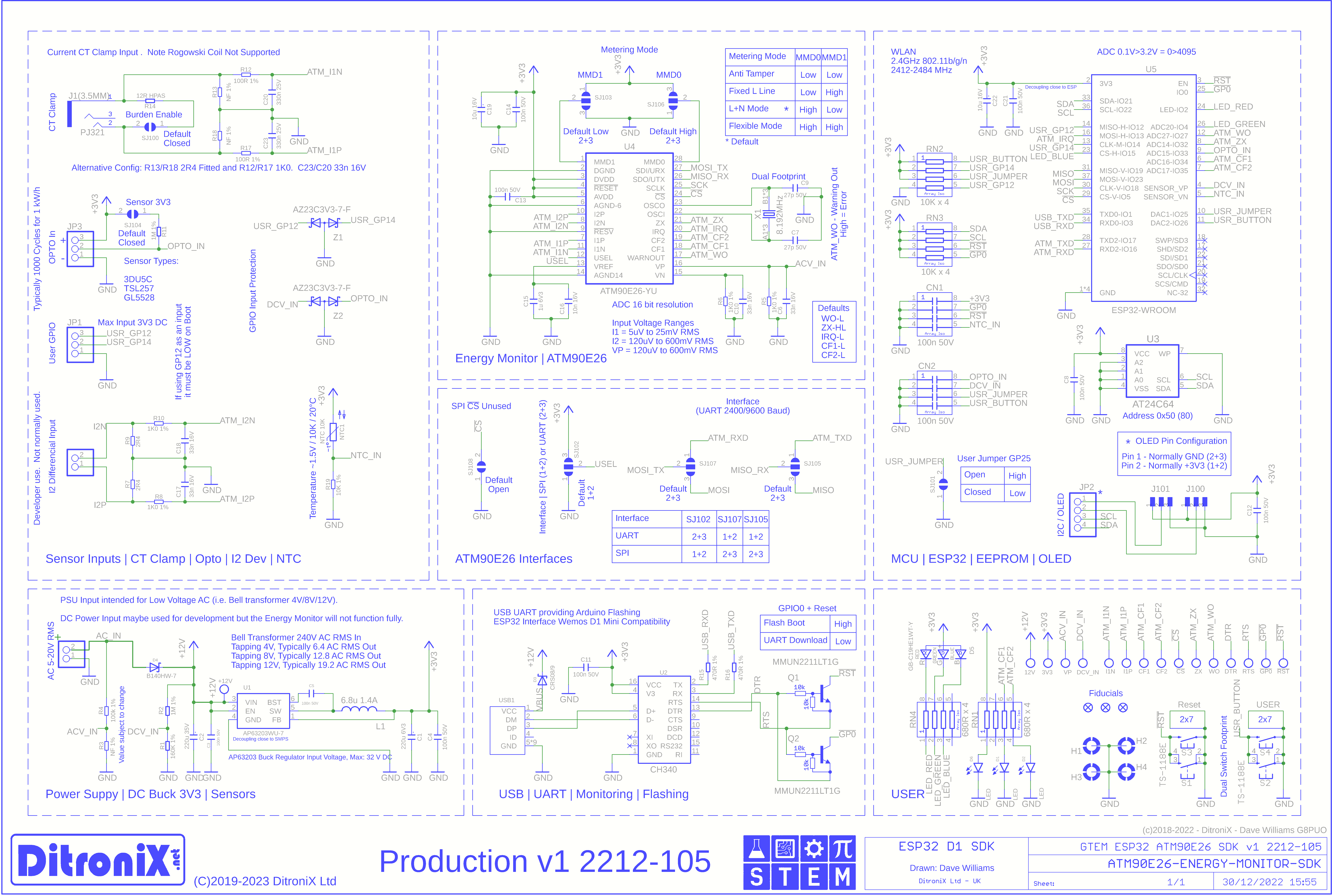
With the increasing interest in Energy Monitoring, we have complimented our Home Automation Solar and Energy Monitoring range of SDK boards, with the new GTEM, which brings together the ESP32 and ATM90E26, to form a very flexibly Home Automation Energy Monitor.
About
The expanding Energy Monitoring projects have evolved over time, due to my being a STEM Ambassador, with interest from electronics enthusiasts, clubs and groups.
GTEM started life a couple of years ago using an ESP8266, CT Clamp and Domoticz. For those of you that have also made these, will have found that they work OK to give Power Consumption but lack the Import (Active) /Export (Re-Active), and Power Factor information. This project also extended into the GTIE SDK (Grid Tie Inverter Extender for SUN-1000GTIL2 and SUN-2000GTIL2 series).
The project expanded over time to include the ESP8266 and ATM90E26, this proving the technology (based and inspired by Tisham Dharon [whatnick] excellent work and enthusiasm), but the ESP8266 lacked additional GPIO and features.
Increasing to processing power and GPIO flexibility offered by the bigger brother, ESP32, is an advantage. For this reason, the culmination of GTEM SDK brought the ESP32 and ATM90E26 together, complete with EEPROM and D1 USB compatibility using the CH340.
Boards Overview
Safety, Safety and more Safety!
An important criteria of the Energy Monitor was the ability to safely and indirectly connect to mains, without working on high voltages.
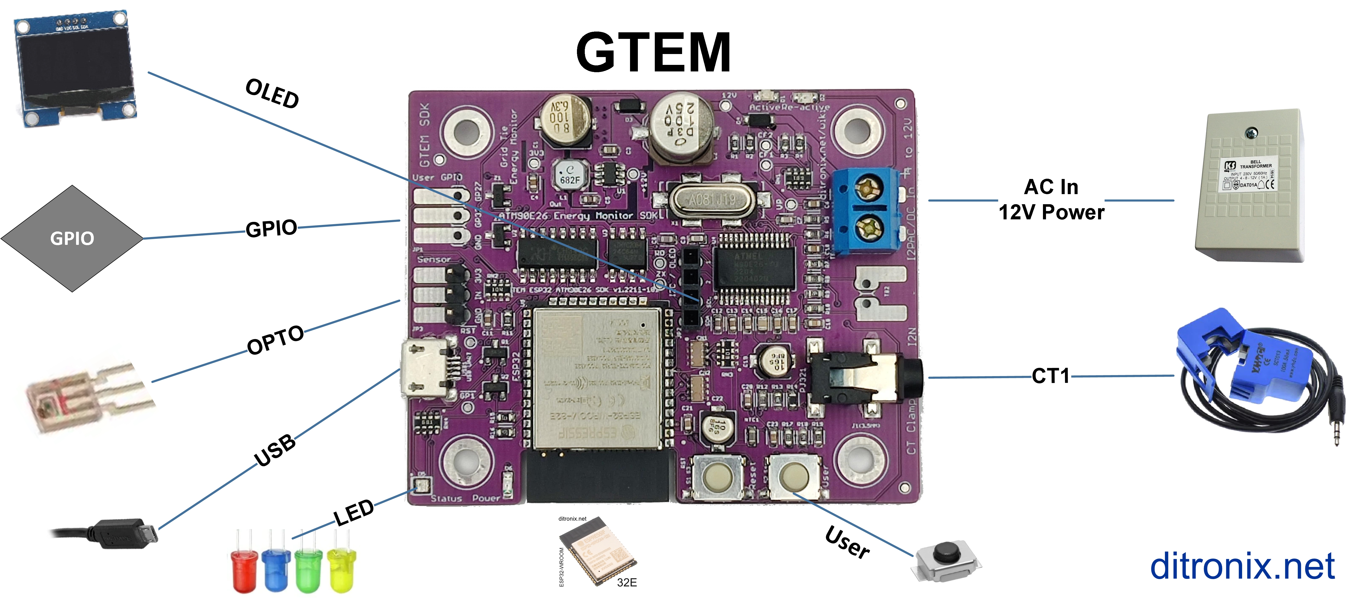
For this reason, the board contains low voltage AC sampling and a DC power supply, both derived from a singe low voltage AC input.
The AC input should be safely derived from a SELV (Safety Extra Low Voltage), 12V transformer. This type of power supply, much like Bell transformers, provides total isolation from the mains as it features a lack of a return path, through earth.
The separate commonly used current clamp simply snaps over a single meter tail cable, so is safety isolated too.
Note: Most wall chargers are either DC output (which is no good) or PELV. To learn more about the differences of SELV and PELV, this video provides a good insight.
Logging and Parameters
Storing parameters ,settings and even local logs is always useful. All our boards include an AT24C64 (EEPROM 64Kb - [8K x 8] Memory IC ).
This is easily accessed via I2C and Arduino EEPROM libraries. The Non-Volatile memory allows for data to be retained, even when power is off. Examples being Wi-fi settings, calibration data etc.
Flashing, Programming and Debug Logging
To make it easier to connect using just a Micro USB cable, the GTEM board includes a CH340 USB-to-serial UART. This IC is commonly used on boards like the Arduino D1 mini, requires no drivers and makes programming and debugging from the Arduino IDE and Visual Studio Code / Platform IO easy.
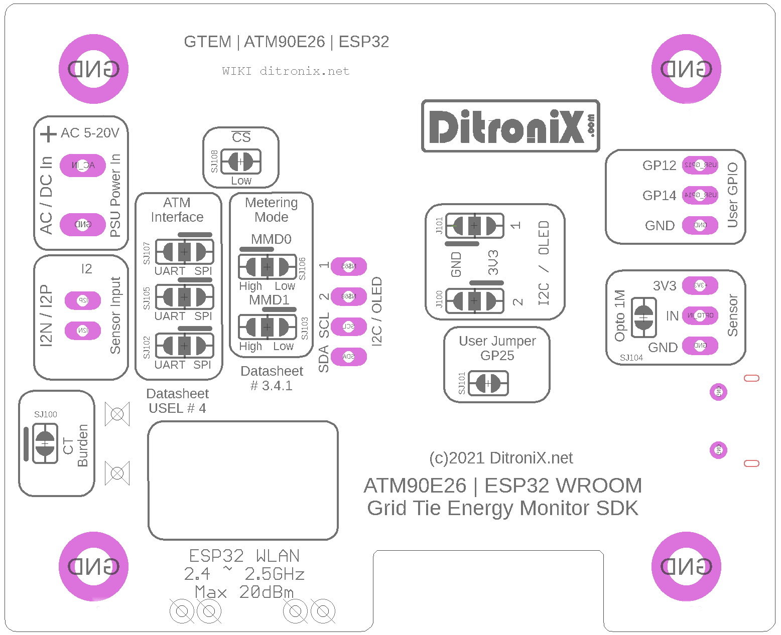
Connections
Availability
The GTEM SDK board is now complete and available. The board uses 0603 components and is supplied fully tested.
Enclosure
The GTEM board is designed to fit into this compact optional enclosure.
OLED
An I2C header is provided on the board, with pin 1 and 2 configurable for Ground and 3V3, in order that it can also be used to connect an OLED display.
Example Code
The board bring-up and beta testing has finished, with integration to Domoticz.
Basic Calibration and Domoticz Code
GitHub with Code Samples and Information
Features
The GTEM Energy Monitoring board main features:
- ESP32 WROOM 32
- Wireless and Bluetooth
- ATM90E26 (Mains Power Energy Monitor)
- ATM90E26 metering features compliance with the requirements of IEC62052-11, IEC62053-21 and IEC62053-23
- Active Energy LED / GPIO Input to ESP32
- Reactive Energy LED / GPIO Input to ESP32
- 24C64 EEPROM (Parameter storage / logging etc.)
- OLED I2C Connector/ Header
- Current Clamp Input
- AC Low Voltage Input
- Power safely derived from a SELV / Wall AC/AC Power Supply
- On-board 3V3 DC Power Supply
- Arduino D1 USB Flashing and Programming Compatibility (CH340)
- OPTO Input - optional Meter Pulse Opto Reader
- On Board NTC (Temperature)
- Reset Button
- User GPIO
- User Programmable Button
- RGB and Power LEDs
- PCB designed to fit into an BMC enclosure
- PCB allows for the display to be included, or not.
- Size 65mm x 53m
In the Box (Fully Tested)
Information
Further details can also be found on our website and wiki pages.
Update 21st May 2023
GTEM has been running for a while now and has a number of users World-wide, together with positive feedback, it offers good functionality and compactness.
The test code, within our GitHub, provides the building blocks that allows the board to be used in a number of both Home Automation and Industrial applications. The two code variations around the GTEM-1_Test_ATM90E26_Basic_Calibration firmware, encompasses all the features of the board.
Should you wish to have more than one CT clamp input, such as for monitoring Mains, Solar etc, then the IPEM may be also good to look at, as it allows for either 3-Phase, or 3 x single phase, with Mains Voltage monitoring.
The board is available to purchase from the website.
Supporting STEM
Life is one long exciting learning curve, help others by setting the seed to knowledge.



_t9PF3orMPd.png?auto=compress%2Cformat&w=40&h=40&fit=fillmax&bg=fff&dpr=2)


Comments
Please log in or sign up to comment.