A precursor to the GTEM Energy Monitor project, was the amalgamation of an ESP8266 and CT Clamp (YHDC Current Transformer SCT-013), which was used to provide feedback of power usage to Domoticz.
Many such projects exist in this area but for a particular requirement, I wanted this to also be portable and not rely on an external power supply.
In addition for another ongoing project, a current clamp extender was required for the Grid Tie Inverters (principally the SUN-1000GTIL2 and SUN-2000GTIL2). GTIE would in effect also be used as the 'current clamp sender' and the forthcoming GTIL project would be the 'current clamp receiver', this board connecting to the GTIL2 Inverter current clamp input and RS232 port in order to gather additional information from the GTIL Inverter.
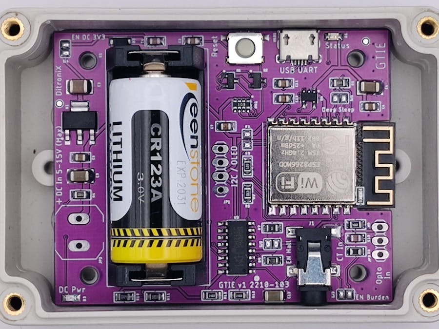
AboutBased on a culmination of needs, the GTIE (Grid Tie Inverter Extender), project evolved and below is the prototype.
GTIE (Grid Tie Inverter Extender) Prototype
As the project also needed to be battery powered, a deep sleep link was added to the board, being powered from a CR123 Lithium Battery, all housed in a small 85x58x33mm Waterproof enclosure for completeness.
GTIE (Grid Tie Inverter Extender) Prototype, in enclosure
For another project, a display was required, so an I2C OLED header was added.
GTIE (Grid Tie Inverter Extender) Prototype, with OLED Display Fitted
GTIE (Grid Tie Inverter Extender) Prototype, Measuring Power to OLED
To extend this project further, it has an OPTO input for optionally reading the Electric Meter kWh flashing LED. For this, a 3DU5C Phototransistor, TSL257 Photodetector or lower sensitive GL5528 Light Dependent Photoresistor can be attached.
Flashing, Programming and Debug LoggingAll my SDK boards now include the standard D1 Mini USB UART so this SDK can be easily controlled via Arduino IDE, or Visual Studio Code/Platform IO and be easily interfaced to a Home Automation system.
FeaturesGTIE v1 board main features (Provisional):
- Grid Tie Inverter Extender for SUN-1000GTIL2 and SUN-2000GTIL2 series
- ESP8266 ESP12S 2.4GHz Wi-Fi
- OLED I2C Connector
- Current Clamp Input
- DC Low Voltage Input
- Powered by CR123 Lithium Battery
- On-board 3V3 DC Power Supply
- USB UART. Micro USB. Uses the popular CH340 for ease of developing code, flashing and debugging.
- Arduino D1 Flashing and Programming Compatibility. No drivers normally needed
- OPTO Input. Meter Pulse Opto Reader
- Reset Button
- User Link
- Status LED (ESP software code / firmware controlled)
- DC Power LED (red)
GTIE in Enclosure with Lid
The GTIE SDK Beta is being tested (Nov 22). The final design and board should be available in December 2022, with SMT complete, or bare bones PCB for those who would like to build and populate it. The board uses 0805 components.
Supporting STEM
Life is one long exciting learning curve, help others by setting the seed to knowledge.


_t9PF3orMPd.png?auto=compress%2Cformat&w=40&h=40&fit=fillmax&bg=fff&dpr=2)


Comments
Please log in or sign up to comment.