Updated 12th March 2025
Project PreambleDuring various Solar energy and Battery Storage System involvements over the years, together with integration of Home Automation for various monitoring and controlling of 'IoT stuff', a new dedicated single board was required in order to more accurately measure multiple DC voltages.
Separate to this, and more importantly, is the ability to safely have full isolation between channels, so multiple battery banks, and strings, for example could be safely monitored using a single board.
Thus, my shopping list of features evolved for this next project.
- Accurately Measure Voltages, from a Positive and Negative Range
- Low Noise
- Good Dynamic Voltage Range
- Self-Contained Board for IoT Projects
- Minimum of Eight Totally Separate Inputs – Each Configurable
- Wide DC Input Power Voltages. Board must be able to be Powered from around 12V to 48V Directly
- Ability to Monitor Lead-Acid, Lithium Batteries. 48V Strings, or Individuals
- Ability to Facilitate Current Monitoring via CT Clamps or DC Shunts
- High Impedance Inputs
- Ability to Measure Sensitive Voltages
- Ability to Measure Temperatures (via Thermocouples)
- Ability to Store Parameters and Log Measurements to EEPROM
- Minimal Calibration Requirements
- Compact but Flexible
- Lower Current Usage
- Controlled using an ESP32 MCU
- Easy USB Connectivity Flashing, Logging etc
Being able to power the board from such as wide voltage range, without the issues of generating heat (so LDO’s were not an option), low noise, and availability, a LM25xx was selected. The range of devices available offer a wide input voltage up to typically 60V and around 52kHz or 150 kHz switching frequencies. The eventual device, cap and inductor values will be evaluated for low noise etc. during development.
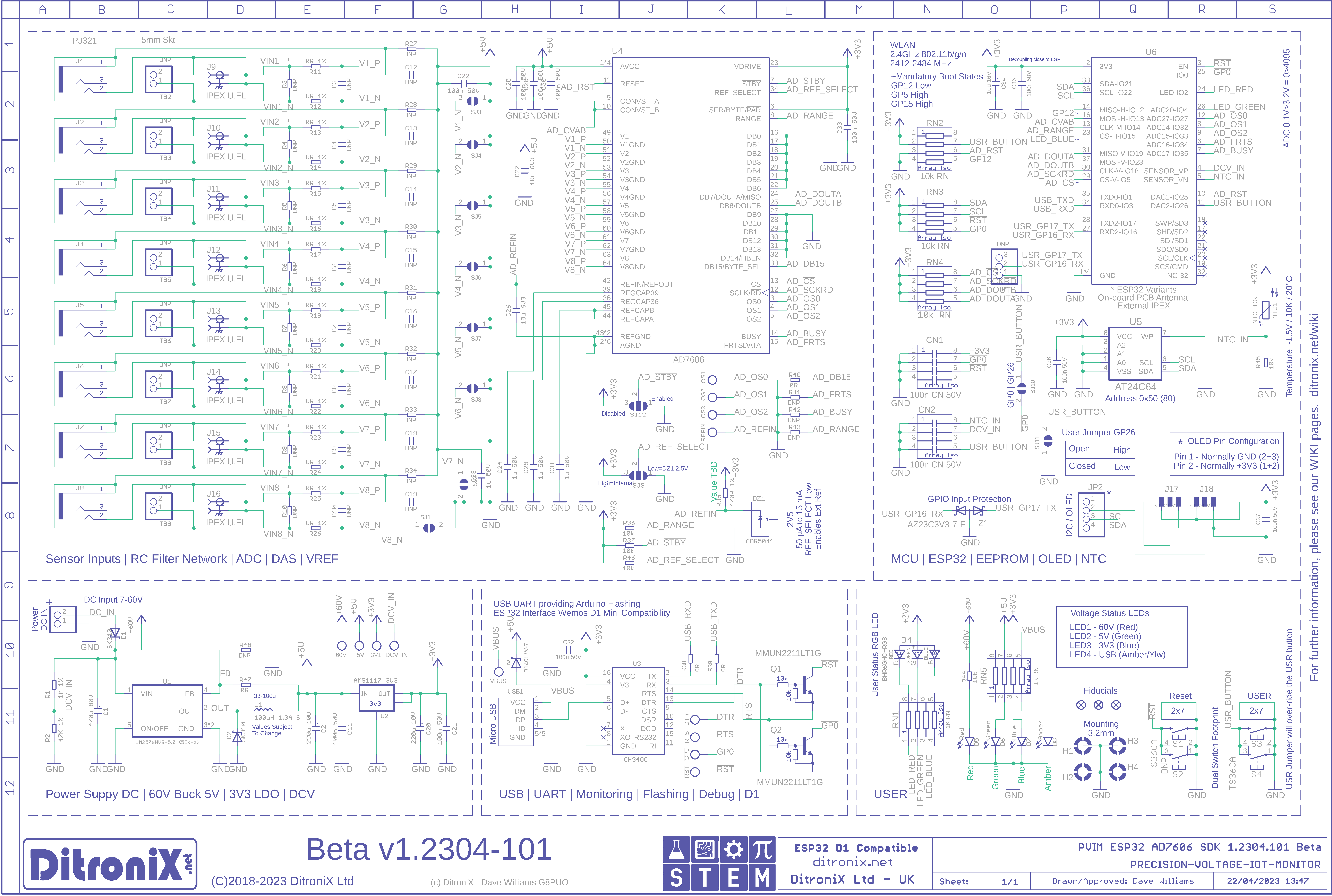
In order to facilitate the wide measurement options, and maintain a single compact board, it was decided to dual foot print the differential inputs using a standard 5mm Terminal Block and a 3.5mm Jack Socket. Additionally, for low level measurements, where sensitivity to noise is possible, provision of coaxial unbalanced inputs was made.
With such as range of input voltage, or current, ranges, an on-board RC filter network to be included, with ability to resistive bias to 5V rail, integrate a potential divider, integrate a Burden resistor and change from balanced inputs to unbalanced inputs.
The ADC DSP DeviceIn researching the vast array of available ADC and DSPs which ticked my wide range of requirement boxes, together with 16bit high resolution sampling of 200 kHz (AD7606BSTZ), importantly being available in stock for SMT, the AD7606 jumped out and this now completed my Swiss-Army-Knife, Precision Voltage Monitor Board.
The AD7606 series offers a wide range of high precision analogue sampling, which could be used for so many electronic and energy monitoring projects. This board is effectively an IoT Digital Volt Meter.
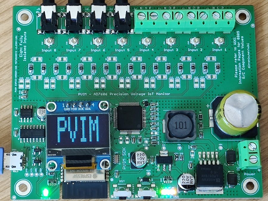
The PVIM project takes this a stage further in pairing the AD7606 (AD7606BSTZ) with an ESP32 (ESP32-WROOM-32E or ESP32-WROOM-32UE), in order to provide a very useful self-contained and compact SDK board.
Data acquisition. Have designed the SDK board with potential future options. This allows for an even higher resolution version for sensitive digital voltmeter, lab measurements using the AD7606BBSTZ (16-bit ADC with 800 kSPS), or even an AD7606C-18BSTZ (18-bit ADC with 1 MSPS on all channels). However, these devices are much more expensive, specialist needs, and not required for mainstream. If you are interested though, please let me know.
Wide Range DC Power InputIn order to facilitate a wide power supply voltage range, PVIM also includes a DC to DC voltage regulator capable of operating from 8 through to 60 Volts. This makes it ideal for monitoring Solar Batteries and Home Energy Systems.
EEPROMAs with all my boards, it must have an EEPROM for east storage of parameters and logging, if required. An AT24C64 is thus included.
The EEPROM sits on I2C, so is easily accessed from the ESP32.
Flashing and LoggingThe PVIM board comes complete with a 'Wemos D1 Mini' compatible USB interface. This enabling easier flashing and no need to have to press a button the flash.
PCB PCAThe PCB is based on 0603 components, where user configurable Resistor Capacitor filter components are 0805 size to make it easier to configure and update values for the desired users project.
The board measures only 100 x 90mm, so is quite compact and although this is a doubled sided (2 layer), board, all components are on the top side.
The normal input options are 3.5mm socket (CT clamps) etc, or 5mm screw terminal header. Each input uses a custom dual footprint which combines the two sockets and reduces the PCB size.
An IPEX U.FL RF connector is fitted. This enables readily available pig-tails to be connected (i.e. IPEX to SMA), so you have screened connections for lower level input monitoring.
The board is effectively split to reduce noise and allow the inputs to be fully configurable.
User configurable solder jumpers are on the bottom board.
- Each channel can be either isolated unbalanced (negative to ground), or isolated balanced (differential pairs).
- The voltage reference is configurable to either the Internal VRef 2.5V or external on-board 2.5V voltage reference.
- OLED / I2C head can be configured so pin 1 and 2 can be set to 3V3 or Ground. This allows for different manufacturers supply configuration.
- Although the board complete with a WeMo D1 compatible interface (so just flash, via the Micro USB, without having to press buttons), the user button can be configured to GP0 or GP25 as needed.
- The AD7606 has a standby configuration, which can be enabled if required.
- ESP32 MCU with integrated Wi-Fi and Bluetooth connectivity
- AD7606BSTZ 8 Channel DAS DSP
- 8 x Simultaneously Sampled Isolated Inputs
- Synchronous Data Acquisition
- 16-bit ADC with 200 kSPS on All channels
- Oversampling Capability With Digital Filter
- True Bipolar Analog Inputs +/- 5 V | +/- 10 V
- Flexible Resistor Capacitor Networks on All Inputs
- Individual Inputs Can Be Balanced (Differential) or Unbalanced (Grounded)
- Second-order Antialiasing Analog Filter
- 7 kV ESD Rating On All Analog Input Channels
- 95.5 dB SNR, -107 dB THD
- 0.5 LSB INL, 0.5 LSB DNL
- Voltage Reference Internal (AD7606) or External (2.5V Reference On-board)
- Board Wide DC Power Input Range 8 to 60V
- USB Wemos D1 Compatible
GPIO
Below is the ESP32 GPIO Matrix for PVIM. This may change slightly, once testing is complete.
The design has been mostly pinned down and a full board laid out.. This is currently in fabrication and expected back, and tested, by end of April.
Status Update (2nd May 2023)The PVIM Beta boards are back, looking really good, populated and now in bring-up testing during next few evenings.
Initial power up is looking good, with draft code flashed and running. All the rails are up, with ESP32 and AD7606 alive and smiling. SMPS, and I/O testing next.
Hopefully all will go fine during testing and production boards could be ordered, ready in around 2-3 weeks - once the design is finalised.
Configuration Examples
Have shown below a selection of photo's of the Beta (green), board, depicting the various configurations.
- 5mm Screw Terminals
- 3.5mm Sockets
- U.FL (to Pigtail and SMA)
- Mixed Connectors
- RC Filters
- OLED example
Photos
Need a good olde cuppa of tea, maybe a biscuit, or two, and back to testing...
Status Update (31st July 2023)The PVIM Beta board unfortunately remains on the bench due to other projects taking precedence. However, plan to get back on this, during August, as quite a bit of interest has been shown.
The board itself is good. A couple of minor tweaks and just software to be developed for testing.- this is where I ran out of time.
Status Update (25th August 2023)It is good to receive so much positive feedback on the PVIM board. Now the holiday period is also almost over, testing and finalisation will resume on the Beta board, hopefully over the next couple of weeks. From here, I can then update where needed and either produce some pre-production boards for community testing, or go straight to production boards.
My biggest delay is time to compete test software and prove the Beta.
Status Update (12th March 2025)Seems a lot of water has flowed under the bridge since I started this project but it is still very much alive.
Whilst the Beta board worked, I want to improve further before finalising it. The changes revolve around and include:
* Increased speed of MCU, such as ESP32-S3 or better ESP32-P4. This will provide better computational speed where high speed data acquisitions are needed.
* Change the USB to the Type C and also update the UART due to obsolescence.
* Tinker with the PSU. Whilst it is OK I want to improve.
* Add Ethernet. This would help in many use cases.
The AD7606BBSTZ (16-bit ADC with 800 kSPS), or even an AD7606C-18BSTZ (18-bit ADC with 1 MSPS on all channels), is still in the shopping list.
KickStarterThis project is planned to be updated and launched on KickStarter in Q2 2025.
FeedbackShould you have any feedback or thoughts, please feel free to contact me.
GitHubFurther details and updates maybe also be found on our GitHub
Further InformationAdditional information, and other technical details on this project, maybe found in the related repository pages.
Repository Folder
- Code(Code examples for Arduino IDE, Raspberry PI, and Platform IO)
- Datasheets and Information(Component Datasheets, Schematics, Board Layouts, Photos, Technical Documentation)
- Certification(Related Repository Project or Part, Certification Information)
Repository Tabs
- Repository Tabs
- Wiki (Related Repository Wiki pages and Technical User Information)
- Discussions (Related Repository User Discussion Forum)
- Issues (Related Repository Technical Issues and Fixes)
We value our Customers, Users of our designs and STEM Communities, all over the World. Should you have any other questions, or feedback to share to others, please feel free to:
Visit the related Project Repositories plus the related Discussions and Wiki Pages. See tab in each separate repository.
Project Community Information can be found at https://www.hackster.io/DitroniX
DitroniX.net Website - Contact Ushttps://ditronix.net/contact/
Twitter: https://twitter.com/DitroniX
Supporting the STEM Projects - BuyMeACoffee https://www.buymeacoffee.com/DitroniX
LinkedIN: https://www.linkedin.com/in/g8puo/
Dave Williams, Maidstone, Kent, UK.
Electronics Engineer | Software Developer | R&D Support | RF Engineering | Product Certification and Testing | STEM Ambassador
STEMSupporting STEM Learning
Life is one long exciting learning curve, help others by setting the seed to knowledge.
Should you have any thoughts, or have a challenging application and would like to beta test a board, please let me know.


_t9PF3orMPd.png?auto=compress%2Cformat&w=40&h=40&fit=fillmax&bg=fff&dpr=2)


Comments
Please log in or sign up to comment.