About: MEGA Development of Automated System is a free community responsible for creating electronic projects and automated systems standing on robotics engineering field which is a breeding ground for creativity an... More About MegaDAS »
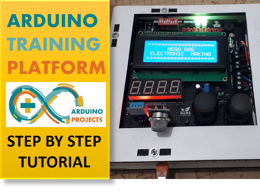
Hey what’s up guys here is again a new tutorial and a new special project, and this time I’ve picked up a real needed project for all electronics maker, today’s project is on how to create your own Arduino training platform, this step by step tutorial will be the best guide for you guys to try this project and for sure there are some basic electronic knowledge required out there but do not think twice to try it because it is an amazing one.
Since quite a while now I’ve been administrating an Arduino Facebook groupand I saw for many many times people were asking about what is the best Arduino kit for practicing and from where to get the best deal to start electronics and a frequent question is about the luck of Arduino kit distributors in some countries, so obviously there is a problem out there which requires our intervene and as a maker I decided to start this tutorial on how to create your own Arduino training platform specially because this project will help me to avoid the wasted time that I spend on wiring the components to the breadboard each time I try to test my codes but instead through having this ready to go platform, life will be easier.
This project is so handy to make specially after getting the customized PCB that we’ve ordered from JLCPCBto improve the appearance of our platform and also there is enough documents and codes in this guide to allow you create your own training bench easily.
We've made this project in just 5 days only, just two days to finish the hardware design for the PCB making and three days to finish the platform assembly and test it as well.
What you will learn from this tutorial :- Selecting the right components depending on your platform
- Making the circuit to connect all the choosen components
- Assemble all the project parts
- Start your first code with this platform
Add TipAsk QuestionCommentDownload
Step 1: Details About the Training BenchThe idea is so simple; I choose some basic electronic components like displays, LEDs, sensors, controllers and different kind of actuators and connect them together through a PCB and keep it all the time assembled and ready for action, a kind of plug and play method.
Features of our platformArduino MEGA2560The main component of this platform will be an Arduino mega2560 which will be the heart of our training bench since it is the linker of all the used components, keeping the signals moving all the way from sensors and controls to the indicators and actuators. This development board is so handy to use and powerful electronic board due to its AVR microcontroller, you can get more details about this microcontroller through this link.
DisplaysI’ve used some displays like a 20x4 LCD display based on I²C communication protocol in order to display some messages and adjust the displayed caracters on this screen and also we are inserting a 7 segment 4 digits display since its is realy needed for beginner to learn how this display works.
ControlsAbout the inputs of our platform we have an 8 switchs bar so we can control some indicators using these switchs without forgetting the two double axes joysticks that has double axes control and a push button, using these joysticks we can control for example the speed and direction of a motor since it has an analog output signal that changes regarding the joystick axes position.
IndicatorsTalking about the indicators, I’ve included 8 Red LEDs and two RGB LEDs and also we have a buzzer there which makes playing with this platform funnier.
SensorsWe can't make a beginner training platform for coding without involving some sensors is it this is why I choosed some frequently used sensors like the DHT-11 sensor for the temperature and humidity, and the gas detection sensor MQ-2 which has also and analog output signal related to the measured gas intensity.
ActuatorsFor the actuators, I decided to insert all types of motors this is why I’ve placed a stepper motor Nema17 and I'm pretty sure that all of you guys need this kind of motors due to its precision and high torque, we are also using a servo motor and two DC motors.
ConnectivityFor the connectivity of our platform I’ve included a Bluetooth module HC-06 in case you want to test an android app installed in your smart phone so this way it will be much easier for you.
ICs and driversFor sure there is some integrated circuit drivers needed to control these components like the MCP23017 to drive the LEDs and L293D H-bridge for controlling the DC motors speed and direction, also I’m using the A4988 stepper motor driver.
Add TipAsk QuestionCommentDownload
Step 2: Project SchematicAll electronic project need a circuit diagram to give an understandable connection between all its sets, this is why we always make this part very importante because this is the main document of the whole project we do.
As show in the picture above we give each components the appropriate connection and links to the main board which is the Arduino MEGA2560, this is very importante to know what kind of connection should be established from the sensors to the board and from the board to the actuator. the circuit diagram could identify also the list of input and output of our training platform, this way it will be easier for begineer to start programming without wasting long time to search for what should be an input and what should be an output.
You can also download the PDF version of this circuit diagram from the file bellow.
AttachmentsArduino training platform_ circuit diagram.pdfDownload
Step 3: The PCB Making (produced by JLCPCB)In order to assemble all the mentioned parts together we require a PCB to establish the right connection from the Arduino board to the indicators and sensors. So I’ve created this circuit diagram and after making the appropriate connection for each component I have transformed this schematic into a PCB design to produce it.
About JLCPCBJLCPCB (Shenzhen JIALICHUANG Electronic Technology Development Co., Ltd.), is the largest PCB prototype enterprise in China and a high-tech manufacturer specializing in quick PCB prototype and small-batch PCB production. With over 10 years of experience in PCB manufacturing, JLCPCB has more than 200, 000 customers at home and abroad, with over 8, 000 online orders of PCB prototyping and small quantity PCB production per day. The annual production capacity is 200, 000 sq.m. for various of 1-layer, 2-layer or multi-layer PCBs. JLC is a professional PCB manufacturer featured of large scale, well equipment, strict management and superior quality.
Back to our projectIn order to produce the appropriate PCB, I have compared the price from many PCB producers and I choose JLCPCBthe best PCB suppliers and the cheapest PCB providers to order this circuit. All what I need to do is some simple clicks to upload the gerber file and set some parameters like the PCB thickness color and quantity, then I’ve paid just 2 Dollars to get my PCB after five days only.
As it shows the picture of the related schemtic, I have used an Arduino MEGA2560 to control the whole system also I've designed the logos and component placement on the board to make the soldering easier for any begineer in electronics making. As you can see in the pictures above the PCB is very well manufactured and I’ve got the same PCB design that we’ve made and all the labels and logos are there to guide me during the soldering steps.
You can also download the Gerber file for this circuit from the file down below in the case you want to place an order for the same circuit design.
AttachmentsGerber_Arduino test Bench_20180617112038.zipDownload
Step 4: Platform Box Design (CAD)Before start soldering the electronic components, I’ll show you this box that I designed using solidworks software which allows me to generate a DXF files to upload them in a CNC laser cutting machine in order to produce the designed box; we used a 5mm MDF wood material to create this box which will add a better appearance to our project, especially with its labels and titles and it will be easier for us to take this training platform with us everywhere we go.
You can download the DXF files for this project from the files down below
AttachmentsArduino training platform_ BOX DXF files.rarDownload
Add TipAsk QuestionCommentDownload
Step 5: Complete IngredientsNow let’s review the necessary components that we need for this project, so as I've said, I'm using an Arduino MEGA2560 to run the whole system.
In order to create this kind of projects we will need :
- The PCB that we have ordered from JLCPCB :
- One Arduino Mega2560 https://amzn.to/2re3XFh
- A NEMA17 stepper motor https://amzn.to/2U13fbw
- Two DC motors https://amzn.to/2PeXHqE
- One servo motor https://amzn.to/2PeXHqE
- One LCD display https://amzn.to/2PeXHqE
- One 7 segment display https://amzn.to/2PeXHqE
- Eight red LEDs https://amzn.to/2PeXHqE
- Two RGB LEDs https://amzn.to/2PeXHqE
- One buzzer https://amzn.to/2PeXHqE
- Eight switch bar https://amzn.to/2PeXHqE
- Two joysticks DHT-11 sensor https://amzn.to/2PeXHqE
- Gas sensor https://amzn.to/2PeXHqE
- Bluetooth module https://amzn.to/2PeXHqE
- MCP23017 integrated circuit
- A4988 stepper driver
- L293D motor driver
- Some SIL header connectors
- Some screw header connectors
- A fuse
- Some resistors and capacitors
- The training platform box
- Some screw for the assembly
We move now to the electronic assembly and we solder all the components to the PCB. you will find on the top silk layer a label of each component indicating its placement on the board and this way you will be 100% sure that you will not make any soldering mistakes.
Now we move directly to the assembly of the box, it is so simple since we created the screw placement in the design, all what we need to do is screwing the PCB to the bottom side of the box in the first step of the assembly.
Then we screw the motors each one to its placement on the top side of the box. Last but no least we connect the motors to them screw headers on the PCB. And finally we finish screwing the other sides of the box.
Add TipAsk QuestionCommentDownload
Step 7: Test (it Worked) :DNow we have everything ready to start playing with this platform and I decided to test some codes like increment the 7 segment display value and turning the stepper motor, the LCD is also working fine so you can see the displayed message on the LCD screen as well.
As you see guys making this amazing project is so handy and following the steps of this instructable makes it easy for any of you guys to try it.
I will show you in the coming instructables the programming part for each component and how to control all these components using the Arduino board.
As usual you can write down your suggestions if you have any other ideas to improve this project and share with us your own training platforms.
One last thing, make sure that you are doing electronics everyday
It was BEE MB from MEGA DAS see next time


_wzec989qrF.jpg?auto=compress%2Cformat&w=48&h=48&fit=fill&bg=ffffff)


_3u05Tpwasz.png?auto=compress%2Cformat&w=40&h=40&fit=fillmax&bg=fff&dpr=2)
Comments