We are a group of 4 ECE students who love to work with cool projects involving electronics. The common thing which unites us is the zeal to learn something new and thereby updating our knowledge in the field of technology. We wanted to begin with something small so that we could cover up the basics, and here we are with our first project involving home automation.
This home automation project is a simple one that we decided to work on, as a way to start our plan to work on bigger projects together. The ultimate aim of this project is to be able to use our voice to control electronic home appliances like TVs, lights, fans, etc. In our case, we decided to demonstrate the idea using Google voice assistant and an LED bulb.
How does this project work?For ease of understanding, let's divide this into sections:
Section 1:Installing the Blynk App.
1. Go to Play Store and install the Blynk app. Once done, create an account and then log into it.
2. Click on 'New Project' to create a new project and then name it according to your wish. Select the hardware device as NodeMCU and connection type as WiFi, while creating the project.
3. After this is done, you will receive an Auth token in your mail. This token will be used to link the Blynk app with the NodeMCU later on.
4. Since we're using a four-channel relay, 4 buttons must be added to the blank project. This is done by clicking anywhere in the blank area and selecting the button from the side menu.
5. These buttons can be named 'Relay1', 'Relay2' and so on for better understanding. Below the names, choose the pin as digital pin D3, D4 and so on correspondingly for the 4 buttons.
5. The Blynk app is now set for our use.
Section 2: Arduino IDE and Blynk Libraries
1. Install Arduino IDE according to your operating system from https://www.arduino.cc/en/software.
2. Download Blynk libraries from https://github.com/blynkkk/blynk-library/releases/ to connect the Blunk app with NodeMCU. Extract the downloaded zip file.
3. Open Arduino IDE, go to File > Preferences and under the Settings tab, copy the sketchbook location path.
4. Open file explorer and go to the copied path location. This is where the Blynk libraries are installed. The newly downloaded Blynk libraries are to be copied into this folder.
5. Copy the files/folders from Libraries folder of the downloaded Blynk directory and paste it into Libraries folder of the Arduino IDE's directory. Similarly so the same for the Tools folder.
Section 3:Upload the code toNodeMCU
1. Connect the ModeMCU to the PC with a USB cable.
2. Open Arduino IDE and go to Tools> Port and use the appropriate port to match the USB port in which the NodeMCU is connected.
3. Next, Go to Tools > Board and select ‘NodeMCU 1.0 (ESP-12E Module)’ as the board.
4. To write the code, Go to Files > Examples > Blynk > Boards_WIFI > ESP8266_Standalone. A new file with some prewritten code will open.
5. Change the line where it says ‘char auth[] = “YourAuthToken”’ and replace it with your Blynk’s auth token that you received in your email.
6. Change the line where it says ‘char ssid[] = “YourNetworkName”’ and replace it with the name of your WIFI network that you want your NodeMCU to connect to.
7. Change the line where it says ‘char pass[] = “YourPassword”’ and replace the ‘YourPassword’ part with the password of your WIFI network.
8. Click the Upload button at the top and wait for the process. The code will be uploaded into NodeMCU and the next time you power it on, it will automatically connect to the WiFi network.
Section 4: Hardware Assembly
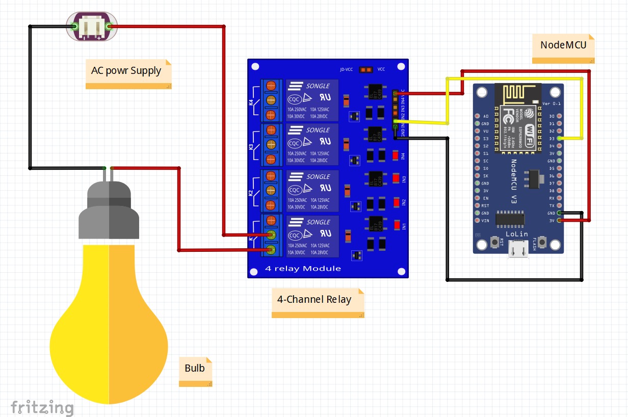
1. Connect the Node MCU with the Relay Board with a breadboard.
2. Connect the D3 pin of NodeMCU with Pin 1 of the Relay. D4 to Pin 2, D5 to Pin 3 and D6 to Pin 4.
3. Connect the ground pin of the Relay to the ground of the NodeMCU.
4. Power the NodeMCU with a normal low voltage phone charger and power up the Relay Board using Arduino UNO board.
5. Four electronic appliances can be connected since we're using 4 Relay pins but in our case, we only used one, an LED bulb.
6. Now this assembly is complete and we can use the Blynk App to turn our electrical appliances on and off with our phone!
Section 5: Connecting Google Assistant using IFTTT
We cannot connect the Google Assistant to the NodeMCU directly. Instead, we send the interpretations of the voice commands to the Blynk App which in turn sends it to the NodeMCU. To make Google Assistant understand the voice commands we make, IFTTT has to be used.
1. Go to https://ifttt.com/ and sign up with your Google account.
2. After signing in click on My Applets from the header and select New Applet.
3. Click on 'this' and search for Google Assistant. Select it and then click to connect.
4. At this point IFTTT will ask you permission to use your google account to add voice commands to it. Click on ‘Allow’.
5. Select the card that says “Say a simple phrase”. Type in the phrases you want Google Assistant to understand as the command. In our case, that could be "Turn on the bulb.", "Turn on relay 1", etc.
6. In the fourth textbox type the reply that Google Assistant should respond with. Then click on 'Create Trigger'.
7. Next, click on 'that' and type webhooks. In the URL field type this URL:
http://188.166.206.43/ YourAuthTokenHere / update / DigitalPinToBeUpdateHere
Replace "YourAuthTokenHere" with the auth token received in your mail from the Blynk app. Replace “DigitalPinToBeUpdateHere” part with the Digital pin of NodeMCU that is to be updated.
So, as we assigned the Digital Pin D3 of NodeMCU to relay one we must write D3 in place of “DigitalPinToBeUpdateHere”. But wait we cannot write D3 there, because when Blynk Server receives this command from IFTTT it assumes as if the command it received was to be sent to an ‘Arduino Uno’ board, but in our case, we are sending it to NodeMCU.hen Blynk Server receives this command from IFTTT it assumes as if the command it received was to be sent to an ‘Arduino Uno’ board, but in our case, we are sending it to NodeMCU. So we use D0 instead.
8. Next, Select the ‘Method’ field as PUT and Select ‘Content type’ as Application/JSON. For the ‘Body’ type this: [“0”]
Here ‘0’ means to turn on, so we are basically saying Blynk to turn on arelay that is connected to pin D3, which in our case is Relay one. Now click on ‘Create Action’ and then Finish.
9. Similarly, we create another applet to turn off the relay.
Once all these steps are done, our registered voice commands can be used to turn on and off the electrical/electronic appliances connected to the NodeMCU.
Here's how our project turned out!


_ztBMuBhMHo.jpg?auto=compress%2Cformat&w=48&h=48&fit=fill&bg=ffffff)


Comments
Please log in or sign up to comment.