


Hardware components | ||||||
_ztBMuBhMHo.jpg?auto=compress%2Cformat&w=48&h=48&fit=fill&bg=ffffff) |
| × | 1 | |||
| × | 1 | ||||
LInterp.h is a pre-processor script to declare and initialise large interpolation / translation / lookup arrays using the Arduino IDE (or any other) C compiler. It declares an array and generates its elements automatically from a set of provided mapping ordinates, and then vanishes leaving no code, data, definitions, classes or anything else behind.This is ideal for Arduino boards with limited RAM as the array may be declared in PROGMEM (program space) memory which is much larger, and no microcontroller code is needed to generate the array. LInterp doesn’t know anything about Arduino boards or bootloaders and is fully hardware independent. It solves the problem of generating potentially large transform arrays virtuallly so the compiler can evaluate the array element values and initialise the array in a single pass. Not bad for a 40-year-old piece of salvage-ware originally written (by the author) as a UNIX shell script to avoid crashing a VAX with similar user-memory limitations.
The most obvious use of LInterp within the Arduino microcontroller platform is the generation of a linear transform for a non-linear sensor or transducer attached to an analog input. By “mapping” a set of values for the analog input (e.g. as voltages at the input pin) over the range produced by the device, LInterp generates an inverse-transformation array whose elements are evenly-spaced points on a user-specified linear function over the same device range. If the interval between array elements is chosen to be greater than the underlying device input scale (e.g. ADC range) then an input value may be translated more accurately by interpolation between adjacent array elements than by just using the nearest-indexed element. LInterp always adds an extra array element at the end of the array to bound the last provided ordinate mapping point above with a valid array element for interpolation (even if the array is declared as flat).
The C-language pre-processor is a primitive text-processing code that works by expanding out and substituting token definitions until they evaluate to constant values. It has no loops, variables or any idea of run-time context and can only do simple integer arithmetic. Fortunately that is just enough to allow the generation of a linear interpolation array from a set of mapping ordinates and input/output scaling parameters. We supply these constants to the pre-processor as #define statements in our Arduino sketch before invoking the script using a #include directive. After the script completes, it deletes all definitions associated with it so a new set may be defined and the script invoked again to generate another array. All tokens in the LInterp script are prefixed with LI_ and will be undefined after it completes, so any array-parameter definitions needed for microcontroller code should be made earlier in the source file and the LInterp token definitions referenced to them. The declared array name is retained by the compiler separately. The #define statement has the following syntax:
#define token value /* assigns value to token */
or
#define token /* asserts that token exists from this point onwards in the source file */
The following list describes the tokens that control the LInterp script. Where the token represents a numerical value, the type is shown in parentheses. Default values are shown in square brackets.
LI_ARR [LInterp] – Name for the array. Retained by the compiler after completion of the script.
LI_CAL (int) – Array base “calibration” scale.
LI_INT (int) [1] – Interpolation interval for LI_CAL.
LI_OFS (float) [0] – Array element constant offset value. Added after scaling (See LI_SCL)
LI_Pn– Array mapping ordinate in the range n=0 to n=32. A minimum of four ordinates must be declared. If more than 32 are needed definitions must be added to the LInterp script (see LInterp.h).
LI_RAM – Force declaration of the array in board RAM even if pgmspace.h is present.
LI_RNG (int) – Mapping ordinate scale for LI_Pn.
LI_SCL (float) [1.0] – Array element scale coefficient, = (last element value) – (first element value) (See LI_OFS)
LI_TYP – Specifies an integer type for the array such as byte, int or long. Elements will be calculated as (float) by the compiler and rounded to (LI_TYP) before assignment to the array.
LI_VAR [const] – Constant / dynamic switch when declaring an array in RAM. Define LI_VAR (with no value) to permit writes to the array after declaration.
The only external dependency of the LInterp script within the Arduino platform is the PROGMEM macro token. If the system header file <avr/pgmspace.h> is not included before the script is invoked, LInterp will declare and initialise the array in RAM as either constant (by default) or modifiable if LI_VAR is defined.
To calculate the array size and element spacing, the pre-processor must multiply and divide the ordinate mapping point values by the supplied scaling and interpolation interval factors, and it must do this using only integer arithmetic as no floating-point type is available to it. Remembering that 999/1000 = 0 in integer division (an underflow), the size and operation order of the array definitions is important to obtain the correct array dimensions. LInterp also converts the supplied constants to long integers within calculations to preclude integer multiplication overflows. When configuring the definition list for LInterp the following numerical considerations should be observed:
Ordinate map scale
The ordinate map definitions LI_P0.. LI_PN and their scaling factor LI_RNG should use a convenient measurement-derived scale that allows the map values to be expressed as integers to the precision required for the array definition.
Array base (interpolation) scale
The integer scale that we wish our array to span, and define our interpolation interval size against, is defined by LI_CAL. It equals the ordinate map scale factor LI_RNG multiplied by a constant, but is provided as a separate factor to allow the use of an existing “natural” index scaling for the array imposed by instrumental or mathematical context.
Ordinate map point array base locations
The ordinate map points LI_Pn (n > 0) do not correspond to array indices directly in general. The array element LInterp[i] that contains LI_Pn (such that (int) i( n ) < (float) i( n ) < (int) i( n ) + 1) is given by
i( n ) = ( LI_Pn * LI_CAL ) / ( LI_RNG * LI_INT )
where the arithmetic operations are performed in the order shown using long integers.
Array size calculation
Using the above array-index calculation, the size of the array is given by the first (LI_P0) and last (LI_PN) mapping points as (# of elements) = i( N ) – i( 0 ) + 1. Again, the arithmetic operators are applied in the sequence shown without prior simplification or grouping of terms. The extra element shown is the added final array element that bounds LI_PN above.
Sufficient ordinate mapping
If the regularly-spaced ordinate map includes a point of inflection of the mapped function (either a peak, dip or saddle point) between successive ordinates, this information is unavailable to the linear interpolator that generates the array elements. Increase the mapping point frequency to resolve such features.
Irregularly-spaced ordinate mapping sets
The ordinate map set {LI_Pn} represents regular intervals of the mapped function being translated. An irregularly-spaced map set {Pn, Sn} of mapping points (PI, SI) is also a regular set, so defining LI_Pi = PI * ( SI – Si-1 ) and Sav as the average value of the intervals ( SI – Si-1 ) within the set produces a regularly-spaced map with ( S0– S(-1) ) = Sav and LI_RNG = [Pnscale] * Sav. Remember that the intervals and Sav must be expressed as integers for LInterp.
Interpolation range limit
The LInterp script includes sufficient interpolation element declarations to provide up to 32 interpolated array elements between successive supplied mapping ordinates.An attempt to declare more than this will produce a fatal compilation error and “interpolation limit exceeded” message. An attempt to declare this many interpolations usually indicates a scaling error in the array definition or a slowly-increasing (low gradient) interval of the mapped function (e.g. P8 to P9 of the graph). As the use of many interpolated values in the array decreases the accuracy of the transform in that ordinate interval, it is best to either declare more ordinate mapping points there (see above note on irregular mapping sets) or increase the interpolation interval LI_INT. If it is deemed absolutely necessary to increase the number of interpolation declarations in the LInterp script, follow the instructions shown in the LInterp.h file.
Ordinate mapping range limit
The LInterp script includes definitions to interpolate between up to 32 ordinate mapping points. If more are needed, the LInterp.h file contains instructions on how to add more mapping point definitions. Note that there are several locations in the file where these additions are needed, not to be confused with interpolation range declarations (see above).
Accessing the array generated by LInterp depends on where it was declared. If it has been declared in RAM it is accessed like any other C array declaration using pointer ( *(array+index) ) or subscript ( array[index] ) notation. If the array was declared in RAM with the LI_VAR token defined, the array elements may be altered by microcontroller code. If the array was declared in program space memory (PROGMEM) it may only be accessed using the functions defined in pgmspace.h to read program-space arrays and the array cannot be altered. These functions have the general form
(array_element_type) pgm_read_array_element_type(int pos);
where array_element_type is a standard numerical type such as byte, int, float or long, and pos is the location in program space memory to read from. To access the ith element in the program-space array produced by LInterp we supply the array name specified with LI_ARR plus i for pos. For future portability and code readability it is prudent to embed the function call within a macro definition such as
#define MyArray( i ) pgm_read_float( LInterp + i )
where the default array name LInterp has been used and the array element type is float in this case. The MyArray() macro may be used just like a function call in code, with an argument that evaluates to an array element index. For more information on the pgmspace.h functions seethe PROGMEM library reference at www.arduino.cc.
If the translation array generated by LInterp is flat (i.e. LI_INT = 1) so that there is an array element for every value of the mapped function, the above macro may be used directly with a bounds-checked value of the mapped function as an array index. If the LInterp array has been specified with an interpolation interval (i.e. LI_INT > 1) so that the mapped function values must be interpolated between array values, an interpolation function must be used to obtain the correct transform value. For example:
float DeviceToLin ( int dev_value ) {
/* lower bound check */
if ( dev_value < ArrOffset ) dev_value = ArrOffset;
/*upper bound check */
else if ( dev_value > ArrLimit ) dev_value = ArrLimit;
dev_value -= ArrOffset;
int index = dev_value / ArrInterp;
/* lower interpolation bound */
float lwr_bound = MyArray ( index );
/*upper interpolation bound */
float upr_bound = MyArray ( index + 1 );
return( lwr_bound + ( upr_bound – lwr_bound ) * ( dev_value % ArrInterp ) / ArrInterp );
}
with ArrInterp equal to the interpolation interval LI_INT used to create the array, dev_value having the same scale as LI_CAL, ArrLimit being the array end position corresponding to LI_PN in LI_CAL units and ArrOffset being the array offset (if any) corresponding to LI_P0 in LI_CAL units (not LI_OFS). The LInterp array generator ensures that the last supplied ordinate mapping point LI_PN is bounded above by a valid array element. Remember to use long ints in any calculation involving array bounds and check for integer overflow warnings from the compiler.
As the most common LInterp application in the Arduino environment would be analog device output translation, an outline header file LinDev.h is provided for customisation against a specific device definition. This envelops the ordinate map, LInterp definitions, device linear transform function and output function in a single header file separate to the Arduino project sketch file, effectively virtualising the device. The following example shows the use of this header file as a stand-alone Arduino sketch.
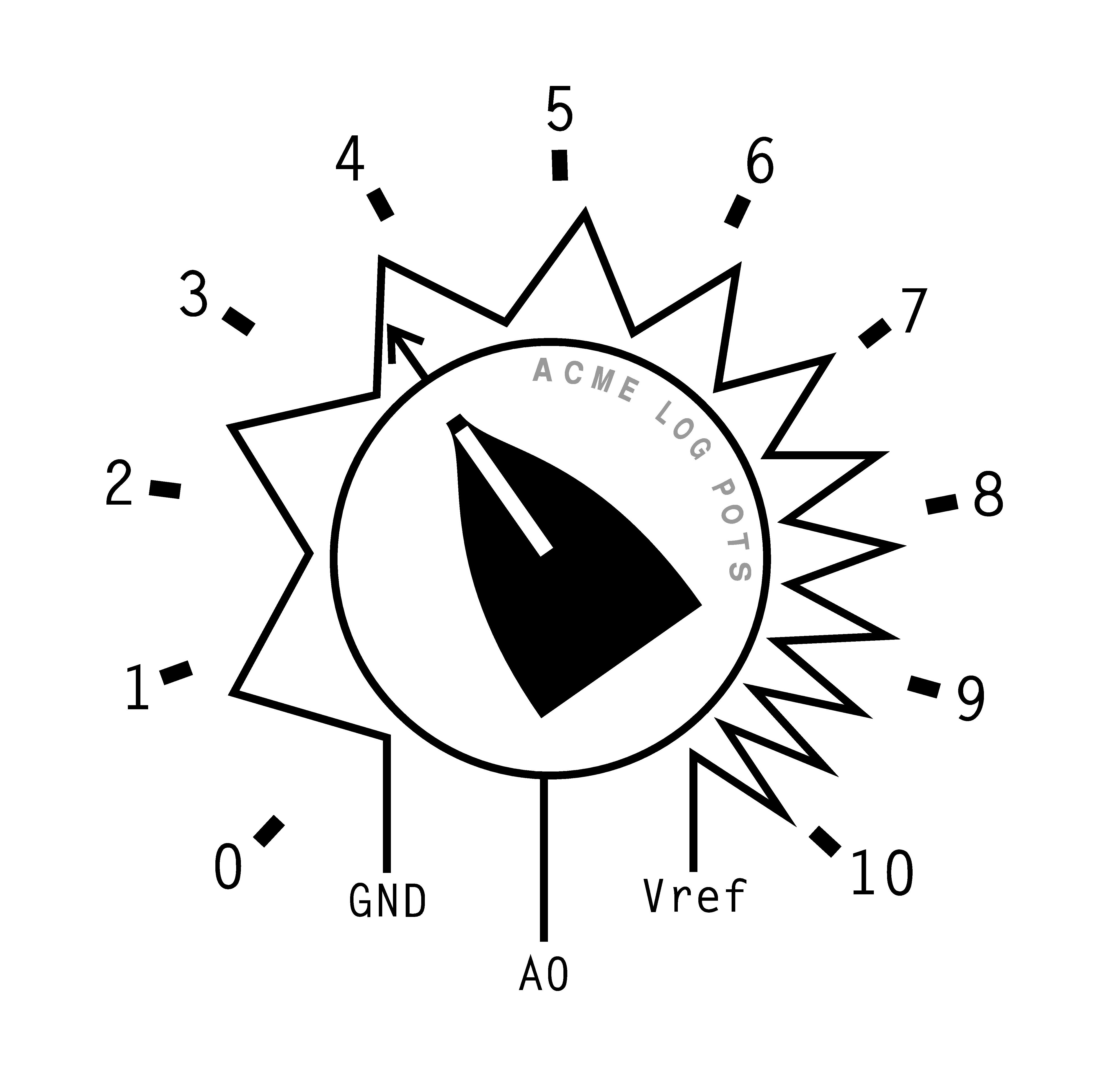
As an example, we consider the use of LInterp to linearise part of the output range of a non-linear analog device attached to an analog input of (any) Arduino board. A logarithmic potentiometer (or log pot) is a variable resistor producing an exponentially-increasing resistance with incremental sweep-rotation angle. If we attach one end of the resistor to ground and the other end to our analog reference voltage supply Vref (sourced from the separately-powered Arduino board), the sweep terminal will produce a non-linear voltage increase with increasing pot spindle-angle as the pot is rotated away from zero, up to Vref at full rotation. Using a 100K pot to limit current drawn from the analog reference supply, fixing the pot to a sheet of cardboard and adding a knob with an orientation pointer to it, we can mark out ten equal-angle intervals around its full rotation range (usually 270 degrees, or 27 degree intervals). If we then measure the pot voltage at each marked position we have a regular ordinate mapping set for the pot. We can then attach the pot sweep terminal to the A0 analog input of the Arduino board and read the pot voltage using analogRead() scaled by Vref divided by the analog channel full-width in ADC levels for the particular Arduino board.
Now, say we want an Arduino-code function that returns the pot orientation angle as a real number between 0 and 10. We could just scale the pot voltage obtained from analogRead() by (10 divided by the analog reference voltage), but the returned values won’t match our marked equal-interval scale around the pot because the pot isn’t linear. We need to use a transform function to “linearise” the pot output. For the sake of our example, let’s also specify that (for some reason) we want the pot transform to be linear between positions 3 and 7 on the scale, but remain non-linear outside this range (but smoothly continuous with it). Let’s also ignore the fact that we know the pot is logarithmic (so we could linearise it with a math function) and require better accuracy between the four marked pot positions than just a linear approximation between them. If we also measure pot voltages halfway between each pot position on our scale, we get a total of nine mapping points to specify as LI_P0 to LI_P8 for our transform array. As these need to be integers, we specify them and also LI_RNG in millivolts, the latter being equal to the analog reference voltage Vref. All log pots should produce the same map shown in the example sketch, as their exponential resistance curves are made to conform to an ANSI standard for log-pot loggyness.
We now select our transform array size based on the range of values produced by the pot, received as ADC levels. Looking at the ordinate map, our desired linear pot-part range covers some 444 ADC levels and would occupy 1780 bytes if declared as a “flat” array. If we adopt an interpolation size LogPotRes of (say) 5 ADC levels we can reduce that to 356 bytes. This is sensible as our ordinate map is too coarse to make valid use of (100 / 444 =) 0.23% resolution accuracy anyway. Accordingly, we set LI_INT to LogPotRes and LI_CAL to the analog channel full-width in ADC levels. Finally, we set the array scale LI_SCL to 10, matching our pot-knob scale, and LI_OFS to 3, being the knob-scale offset of all the array element values from where we specified the array to start with LI_P0. We will also keep copies of LI_P0 and LI_P8 (in mV, as long ints) to locate the start and end of our linear pot-part in the transform function. We now invoke the LInterp script using the #include directive, after which our array is allocated, initialised and visible to our code and all the LI_ definitions are deleted.
Using the serial port connected to the Arduino board, we can now examine the declared array from within the setup() function, shown as if it were a conventional array declaration in program code. Note that the first element equals our definition of LI_OFS, and the last element is (just) greater than LI_OFS + LI_SCL. The function ReadPot() takes an average over several readings of the pot analog channel and performs a bounds-check on the pot voltage. If this is outside our linear transform range, the voltage is just scaled against the relevant knob-interval range and returned; otherwise it is array-transformed as per our DeviceToLin() function example. After starting the loop() function, the pot-knob positions should be reported correctly within the range 3 to 7, and approximately outside this range.
ovf,inf and nan values returned near the end of the array
When scaling analog device levels into array indices, beware of discrepancies with the original ordinate-mapping reference voltage. ADC levels scaled directly into array indices may exceed the end of the array if either the ADC or analog device reference voltages have drifted relative to the mapping reference voltage. For this reason, it is always a good idea to use a common external reference voltage supply for your analog devices and the Arduino board ADC (via the AREF pin). If device voltage drift is an unavoidable constraint in your Arduino application, dedicate an analog channel as a device voltage monitor and scale against it in your transform-array index calculation. Similarly, assuming a nominal value for LI_RNG rather than an accurately-measured value may result in an array being too short when accessed with a device-derived array index. (Tech note: remember that the ADC always returns 1LSB less than Vref at full scale.)
Array declaration produces one array element (=LI_OFS)
Choosing scaling ranges for LI_RNG and LI_CAL that result in integer division underflow errors can make your entire array disappear. (See Ordinate scaling and integer arithmetic)
Missing / overlapping values at array boundaries
When using a translation / interpolation array declared over part of a device range as in the above example, care must be taken in how the boundaries of the array are ascertained by the transform function code. This should be done using the same integer values (as long ints) used to define the array relative to LI_CAL rather than bounds-checking the calculated array index, which can introduce truncation errors.
The LInterp script may be customised to produce an output array encoding a non-linear output function within the severe limitations imposed by the limited abilities of the pre-processor. This may be achieved using macro definitions of the form
#define LI_OFS( curr_map_pt, next_map_pt, element ) ( /*... arithmetic operations */ )
#define LI_SCL( curr_map_pt, next_map_pt, element ) ( /*... arithmetic operations */ )
and replacing (one or both) LI_OFS and LI_SCL in the element generator at the top of the LInterp.h file with these exact statements:
LI_OFS( LI_LEV, LI_NXT, LI_ELT )
LI_SCL( LI_LEV, LI_NXT, LI_ELT )
as well as changing the first element shown in the array declaration initialiser list to LI_OFS(0, 1, 0) (or a hard-coded #define numerical constant) if LI_OFS is changed to a macro.The numerical tokens (not variables) LI_LEV and LI_NXT specify the LI_Pn and LI_P(n+1) map entries between which LI_ELT numerical tokens are defined for each interpolation interval (if any), starting with 1 and ending with as many whole intervals fit within the range. The token LI_NXT always equals LI_LEV + 1 and is necessary because the pre-processor can’t add 1 to a token. Note that the first array element shown above is a special case, with an unique element value of 0 which may be detected and handled with a conditional test such as ( ( element== 0 )? .. : .. ) using the ternary operator in the macro. These three numerical tokens are the only context information available to the pre-processor in the LInterp script.
Fortunately, the LI_OFS and LI_SCL macros are only evaluated in the compile pass where the passed numerical tokens evaluate to integers and floating-point arithmetic operations are permissible as well as type-conversions and casts. This provides a limited ability to calculate an output function within the context of these three “state” tokens only. The mapping-point distribution now becomes a domain for the output function, complicated by the fact that interpolation allocations to each mapping interval will change according to its range. Given that the element generator will still calculate linear fractional values that multiply LI_SCL for the interpolated array elements, the output function need only be defined in terms of LI_LEV if linear approximations between mapping points are sufficient for the accuracy of the output function.As a somewhat trivial example, a parabolic output function may be defined by
#define LI_SCL(p,q,r) ( scale_constant * p * p )
and leaving LI_OFS as a constant definition. The scale_constant can be a real number supplied as a token from another #define statement. A far more useful example of an output function macro definition would be changing the linear output function for a single region of the transform array defined by upper and lower bounding entries in the ordinate map:
#define LI_OFS(p,q,r) ( (p < LWR) * OFS1 + (p >= LWR && p < UPR ) * OFS2 + ( p >= UPR ) * OFS3 )
#define LI_SCL(p,q,r) ( ( p < LWR || p >= UPR ) * SCL1 + ( p >= LWR && p < UPR ) * SCL2 )
where the expression tokens are user-supplied #define constants, with the offsets OFSi chosen to render the three linear sections continuous at the ordinate map entries numbered UPR and LWR. The same array may then be used to produce different output functions transparently based on input indexing alone, instead of using three arrays and coding input bounds tests to choose between them.
The macro interpolation-element number token (corresponding to LI_ELT) is somewhat useless without prior knowledge of its range. This may be obtained from the LI_S() macro and used to produce a real fractional range-factor for the current array element:
elt_factor = ( (float) element /
(long) LI_S( curr_map_pt, next_map_pt ) )
where element runs from 1 to LI_S() and the 0th element is defined as the last element of the previous mapping interval, or the first element of the array.
Please rename the header file containing your customizations, as mutant LInterp variants have a habit of escaping from the lab disguised as standard-specification versions and causing panic amongst the townsfolk. In particular, please do not annoy the Arduino support staff or forum moderators with questions about pre-processor scripting, which is an arcane and rightly lost (black) art. Sadly, you will find ample assistance in C-programming forums such as GitHub or StackOverflow (the latter of which was named for a common result of erroneous pre-processor scripting).
Historical noteLInterp comes to the Arduino environment via an evolutionary process through many hardware platforms, from Beowulf clusters to GPU boards, and doubtless has been re-invented many times. It is likely that scripts like LInterp are a historical reason why the ANSI standard for the C pre-processor has remained so highly restrictive of its functionality. Apologies in advance to anyone who considers they deserve credit for its derivation; however the author attests that the provided LInterp script and associated codes are totally their own work and free of any copyright liabilities (and has evidence of such, probably on magnetic tape). It is provided in the “copyLeft” spirit of free open-source public distribution. The author accepts no liability for any results of its use.
Happy interpolating,
dxb
(Ancients of Code)

_3u05Tpwasz.png?auto=compress%2Cformat&w=40&h=40&fit=fillmax&bg=fff&dpr=2)
Comments
Please log in or sign up to comment.