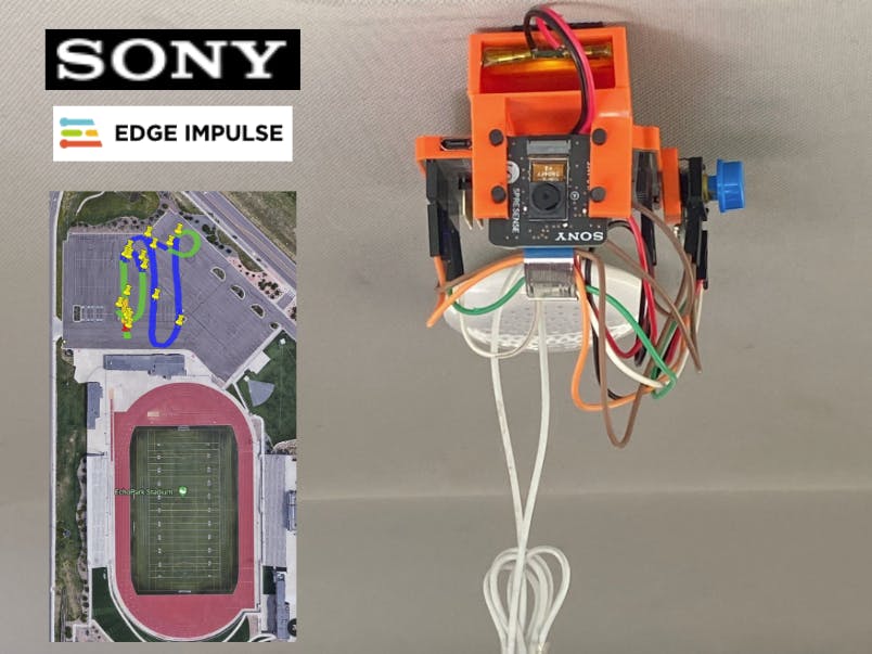
Our 10n2 project aims to identify poor driving habits through the use of Sony Spresense and AI. Young drivers can and do pickup many poor habits at a very young age. Poor habits can range from improper hand position to using cellular devices while in control of the vehicle. The National Safety Council reports that cellphone usage contributes to 1.6 million crashes each year! With a new driver in the making, we are very interested in helping to squash poor driving habits before they become routine.
AI and IoT to the rescueThe 10n2 device will not only detect cellphone use, but also improper hand position, tight turns, short stops fast accelerations and pot hole hopping. All of which can contribute to dangerous driving conditions. Drivers are notified in real-time when a violation is detected.
The information collected by the device is used to generate a report in Google Earth KML that detail the detected violation along with geographic location. Violations are collected and a score is calculated at various segments of the trip. Drivers can review their trip and understand where they can make improvements.
Building the Device10n2 is a combination of 3d printed materials, DiY electrical components, Sony Spresense board and camera, an Edge Impulse trained CNN and some code to make it all work.
10n2 Mount
The first thing to do is print the 10n2 mount. Load the model.stl into slicing software (such as Cura), and generate the gcode used by many 3d printers. Once you have the gcode, load it onto your 3d printer, the print takes roughly 1 hr. on a Ender3 Pro!
Spresense Preparation
Now it's time to prep the Sony Spresense by following the awesome documentation from the Sony website. Once you have your Spresense up and running, and the Sony camera board installed, it's time to solder the battery receptacle to the main board.
Install components
The next step is to install the MPU and button switch. The 10n2 mount has mounts for both the MPU as well as the button. The MPU is secured using an M3 screw and the button is mounted directly to 10n2 mount using Velcro.
Wire Components
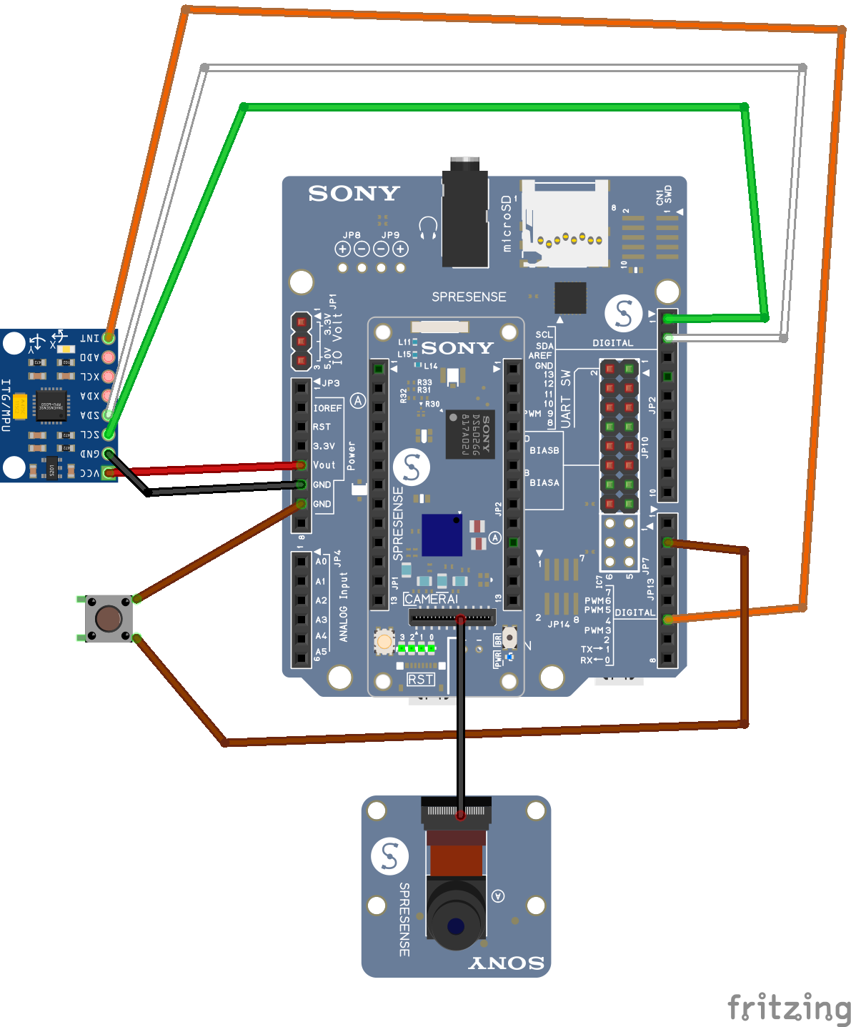
Now that the components are mounted, you can wire up both the MPU and the button per the wiring diagram below. Wire management can be achieved by running the wires under the camera ribbon cable. This keeps the wires out of your way and helps with the GPS signal.
Finishing Touches
With the device all wired us, we can now install the battery housing and Velcro (used to mount the 10n2 device to the car roof). The battery housing is glued to the bottom of the camera mount. This serves two purposes; 1) to hold the battery (duh) and 2) to provide the correct angle for the camera to capture images and perform the real-time classification. You can also install a lightweight 3.5 mm. jack speaker as this point.
Congratulations! You're now down with the hardware.
Load the 10n2 softwareThe 10n2 software is all available on GitHub. To load the software it's recommended that you follow the Spresense SDK setup, clone the repository and install the software directly to the device using VSCode.
IDE Preparation
Follow the Sony Spresense IDE guide to get the software installed and configured for your environment.
10n2 Preparationand Build
Now that you have an IDE ready to go, it's time to clone the 10n2 repository. Clone the repository to a new VSCode project. The 10n2 repository has a 10n2 sdk.config that has all the nuttx/spresense configuration required to run the 10n2 software. Connect your Spresense device to your computer through the micro-USB and ensure it's recognized by VSCode. Now you can flash your device by left clicking your VSCode project and selecting Spresense: Build and Flash.
If all goes well, and there are no issues, you should have a 10n2 device ready for use!
Mount 10n2
10n2 needs to be mounted upside down and roughly 12" behind the driver's head and centered between the doors with about a 15 degree downward pitch (provided by the battery mount).
The 10n2 device uses Edge Impulse to design model and train the CNN at the heart of 10n2. The model is a simple 3 class (hands/no hands/cell) 2D quantized convolutional model. We decided to go with a simple CNN because of the memory/compute restrictions of the Sony Spresense. Quantization was essential as it got the model to a manageable size. Edge Impulse has an easy to use method for quantizing models and great instructions on how to use the quantized model on the target hardware.
As you can see, the model trains relatively well and performs surprisingly well.
Data
The model is trained on 96x96 bit images grayscale 8-bit images. We chose 96x96 as it was just large enough to cover the steering wheel in the field of view, small enough to make comfortable sized model for our target platform and 96x96 is a common sizing amongst many popular pretrained models.
Data Collection
Data was collected* directly from the Spresense and Sony Camera board. We use the pixels from 192-288 in the Camera's x coordinate and the 12-108 in the Camera's y coordinate for our 96x96 down sample. This lies in the camera's top right quadrant that is the quadrant that covers the steering wheel and hand position.
* All data was collected in a 2007 Honda CRV
Installing EI Model
Once you have a model you're comfortable with, you can use the awesome Edge Impulse website to build a deployable model. The 10n2 project uses the C++ model deployment method.
Once you have the C++ model deployment zip, all you need to do is extract the following files to their equivalents in the 10n2 repository:
model_metadata.h
tflite-resolver.h
tflite-trained.h //model weightsMy favorite part of any project is the code! The 10n2 code in its entirety is available via GitHub. This section will highlight the import parts. Firstly, SMP was required as 10n2 requires a lot from the Spresense. SMP allows for asynchronous use of all 6 cores. 10n2 dedicated a full core to the TensorFlow inference engine, and divvied up the remaining cores for things like camera captures, data collection and KML generation.
SMP Example
You'll notice that it's important to set the CPU affinity when you're utilizing SMP. This tells the scheduler which CPU to run the p-thread.
bool imu_init(void)
{
    printf("imu init\n");
    imu_running = true;
    cpu_set_t cpuset = 1 << 2;
    pthread_create(&imu_th_consumer, NULL, &_imu_q_read, NULL);
    int rc;
    rc = pthread_setaffinity_np(imu_th_consumer, sizeof(cpu_set_t), &cpuset);
    if (rc != 0)
    {
        printf("Unable set CPU affinity : %d", rc);
    }

    return true;
}
Edge Impulse model inference
The TFLM model generated by EI is quantized. The inputs and output must be quantized and dequantized to get meaningful results.
Quantize
int8_t quantize(uint8_t pixel_grayscale)
{

    // ITU-R 601-2 luma transform
    // see: https://pillow.readthedocs.io/en/stable/reference/Image.html#PIL.Image.Image.convert
    int32_t gray = (iRedToGray * pixel_grayscale) + (iGreenToGray * pixel_grayscale) + (iBlueToGray * pixel_grayscale);
    gray >>= 16; // scale down to int8_t
    gray += EI_CLASSIFIER_TFLITE_INPUT_ZEROPOINT;
    if (gray < -128)
        gray = -128;
    else if (gray > 127)
        gray = 127;
    return static_cast<int8_t>(gray);
}
Dequantize
for (int k = 0; k < NUM_CLASSES; k++)
      {
          //dequantized output
          conf = (od[k] - EI_CLASSIFIER_TFLITE_OUTPUT_ZEROPOINT) * EI_CLASSIFIER_TFLITE_OUTPUT_SCALE;

      }
The tight turn, acceleration and deceleration are all computed from data collected by the MPU. The MPU is mounted on the side of 10n2 with its Z axis up, Y axis along the acceleration axis of the vehicle and its Z axis orthogonal to X and Y.
Acceleration/Deceleration
Acceleration and deceleration are computed by determining the slope of the Y samples over moving.35 second window of 100 Hz. samples. If the slope is above a threshold, then the vehicle is considered to be accelerating too fast. If the slope is below a threshold (+- 500), then the vehicle is considered to be decelerating too fast.
Tight Turns
Turns are computed the same way as acceleration but by using the X accelerations from the MPU and using a much smaller slope threshold (+- 250).
Pot Holes
Pot holes are identified by using a standard deviation threshold on accelerations along the Z axis. If the standard deviation is > 1800 then we consider this a pot hold.
Collected Data10n2 records the raw sensor data as well as the calculated data in csv. When 10n2 is in 'training' mode, the image data is collected as well. CSV data is stored in the following CSV format:
t	slopex	slopey	slopez	inf	conf	acx	acy	acz	gyx	gyy	gyz	y	M	d	h	m	s	us	type	lat	lon
23915	-98	55.299999	-27	0	0.53125	4225	-210	644	205	-129	-54	2022	8	3	23	42	23	586585	1	39.513708	-104.764668
24016	17.1	44.599998	-15.6	2	0.589843	4949	-4	641	-71	-75	20	2022	8	3	23	42	24	817926	1	39.513708	-104.764668
24117	-11.2	-31.700001	-6.1	1	0.46875	4870	-99	713	-53	-196	32	2022	8	3	23	42	25	433078	1	39.513708	-104.764668
24218	-67.400002	-35.200001	-7.1	0	0.953125	4969	10	685	-60	-104	-2	2022	8	3	23	42	26	648016	1	39.513708	-104.764668
24321 -12.1 7.8 6.6 1 0.734375 5005 -44 704 -60 -120 15 2022 8 3 23 42 27 890861 1 39.513708 -104.764668If you made it this far, thank you. We had a great time developing what we believe to be a useful product. We welcome all comments and questions and hope you enjoy 10n2. To check out more information, please visit us online.


Comments
Please log in or sign up to comment.