

Hardware components | ||||||
 |
| × | 1 | |||
 |
| × | 1 | |||
 |
| × | 2 | |||
 |
| × | 1 | |||
 |
| × | 1 | |||
| × | 1 | ||||
| × | 1 | ||||
 |
| × | 1 | |||
 |
| × | 1 | |||
Hand tools and fabrication machines | ||||||
 |
| |||||
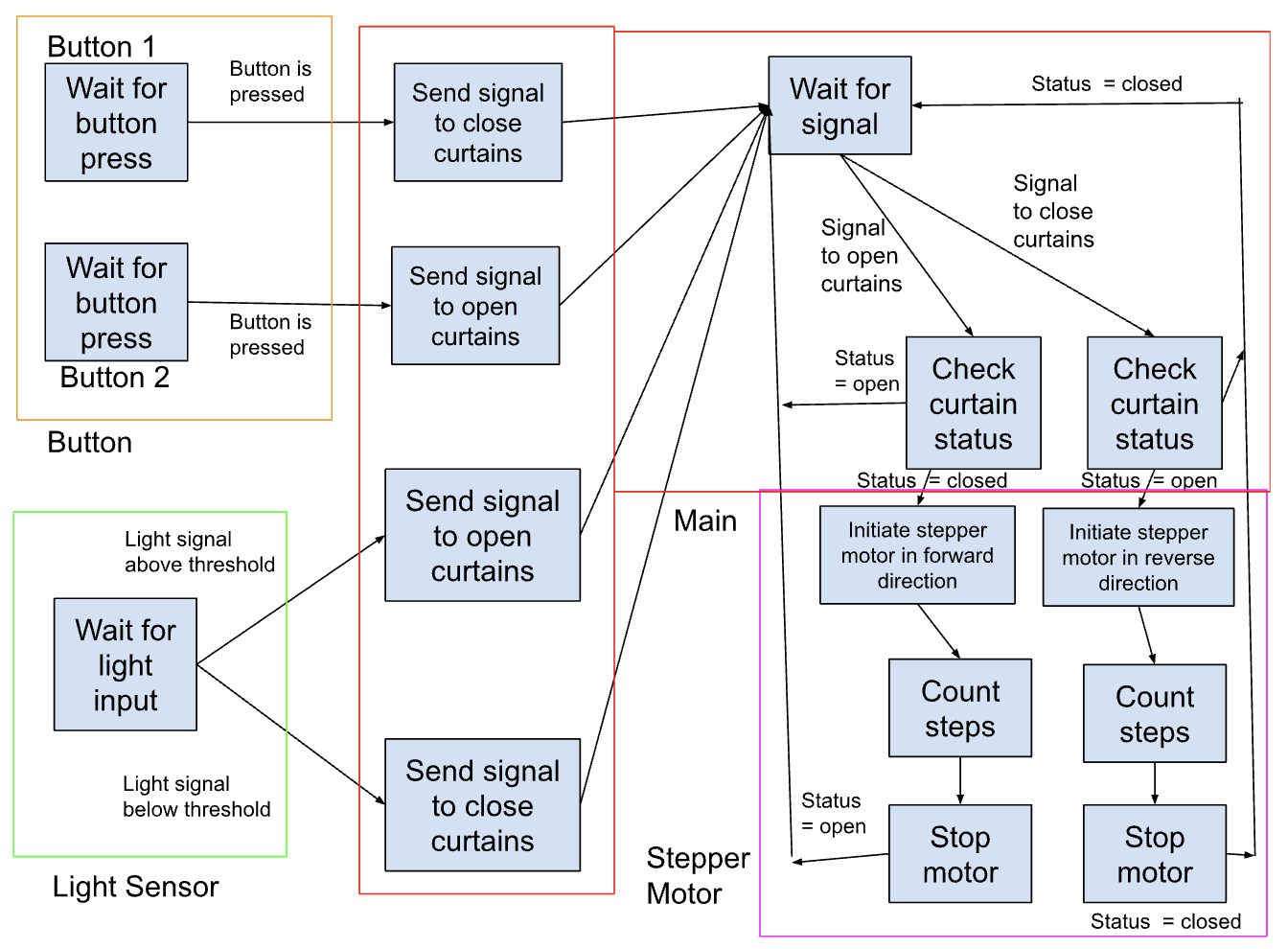
This project is intended to use a Pocket Beagle, light sensor, and stepper motor to automate curtain opening in response to light. I was inspired by the remote-controlled curtains at a family member's house. Those curtains could be opened or closed using the remote, but still require the user to open/close them. I wanted to recreate this feature with the addition of a light sensor that could allow the curtains to open automatically when the sun comes up in the morning. I am an early riser, and I thought it would be better to wake up naturally with my circadian rhythm than to a loud, annoying alarm. Thus, the idea for Smart Curtains was born!
Current Progress:I was able to build the project with a light sensor, stepper motor, and two buttons. One button opens the curtains, and the other button closes the curtains. The light sensor is set to where light above a certain intensity threshold triggers the curtains to open. They can then be closed using the button. The Pocket Beagle receives input from the buttons and light sensor. The Pocket Beagle then prompts the stepper motor to either rotate forwards or backwards a pre-specified amount of steps set by the user. This constant would depend on the type and dimensions of the curtains being used.
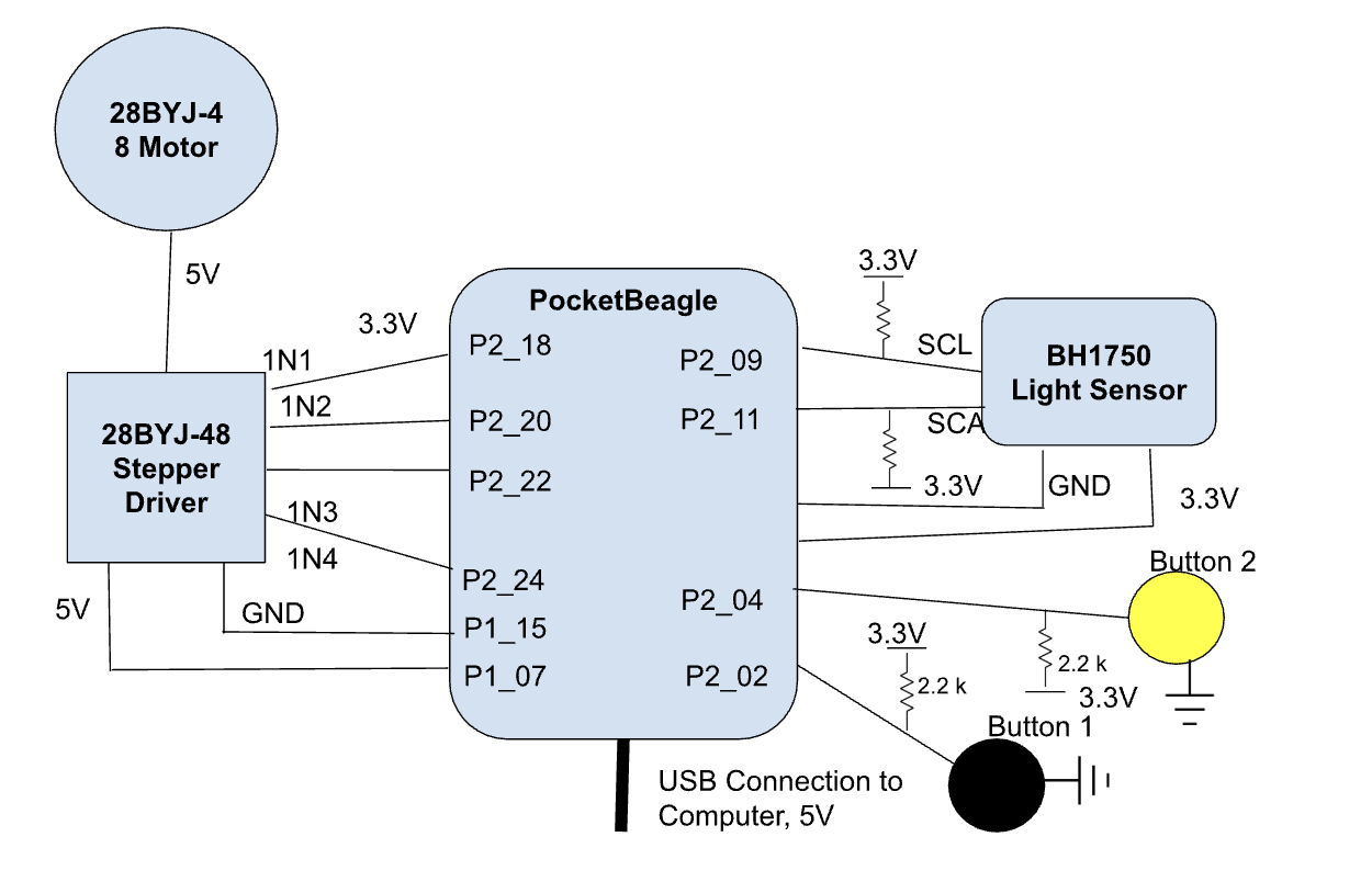
Instructions for Build:Flash SD card with standard PocketBeagle operating software and insert into the SD card holder. Place PocketBeagle with expansion headers onto generic breadboard.
Connect negative rail to P2_21 (GND) and positive rail to P2_23 (3.3V output).
3.3V output will be used to power light sensor and both buttons.
Use the pin connector included with the BH1750 light sensor to connect it to the breadboard; take note of pin locations. Connect Vcc pin to 3.3V rail. Connect GND to ground rail. SCL and SCA pins should be connected to 3.3V rail using 4.7k resistors, but leave room to include jumper cables to the GPIO pins. Connect SCL to P2_09 and SCA to P2_11.
Next, connect two push buttons to the breadboard. Both should be grounded on one end, and the other end will connect to GPIO pin with 2.2k Ohm resistor connecting it to 3.3V rail.
Here, the black button corresponds to closing curtain mechanism, and the yellow one will open the curtains. Connect black button to P2_02 pin of Pocket Beagle and yellow button to P2_04 pin, both using jumper cables.
For the stepper motor, first make sure the motor terminal block is connected to the matching terminal block on the stepper motor driver. Next, connect female to femal jumper wires to power pins and all 4 GPIO pins.
Wires for power and ground should be connected to P1_07 (Vin, usb) and P1_15 (GND) on the Pocket Beagle. The rails on the opposite side of the breadboard can be used for this. You will need to connect male-male jumper cables to the female-female jumper cables, or simply use female-male jumper cables and then you won't need to connect two together.
Next, connect the jumper cables for the GPIO pins to the PocketBeagle. 1N1 is P2_18, 1N2 is P2_20, 1N3 is P2_22, and 1N4 is P2_24.
Finally, plug in the USB to USB micro cable into your personal computer on one end, and into the Pocket Beagle USB terminal on the other end. You can now download and run the software for this project.
Please see the smart curtains Github entry for detailed instructions. Program needs to be downloaded by the user and will not reset or require maintenance once running.
Future Development:Current power configuration for the stepper motor and driver may not be adequate. Connecting the driver to the PocketBeagle pins described in the block diagram is not consistent and often causes the LEDs on the PocketBeagle to turn off. Ideally, an external power supply should be used for the power pins of the driver instead, to give the motor a reliable 5V. The GPIO pins should be sufficiently powered by the PocketBeagle. A switch should be integrated into the light sensor to give the user the opportunity to turn the sensor on and off (in case they want to sleep in). Additionally, a potentiometer and 8 bit display could be integrated along with the appropriate python code to enable implementation of a timer, such as waiting X amount of minutes after the minimum light threshold is reached to open the curtains. This would give the user more control over when they want to wake up. Finally, it should be noted that the actual curtains were unable to be integrated into this device at this stage. The stepper motor has a bolt/bar where strong string, such as fishing wire, can be attached. This would be attached to the curtains or blinds in such a way that as the motor rotates, it pulls the curtains/blinds open or closed, depending on which way it rotates.


_3u05Tpwasz.png?auto=compress%2Cformat&w=40&h=40&fit=fillmax&bg=fff&dpr=2)
Comments