


Hardware components | ||||||
| × | 1 | ||||
| × | 1 | ||||
Software apps and online services | ||||||
 |
| |||||
Some time ago, I did some experiments creating an oscilloscope using various boards, here the link, where I tested different methods, external adc and bypassing the Arduino ADC standard commands and writing directly to the registry. This time, the ADC works only on DMA, using all the functionalities provided by the stm32h747xi controller. The ADC section, contains 3 ADC with variable resolution, with 2 of them able to join in interleaved mode, doubling the sample rate. In this way, I was able to observe and measure a 12 MHz signal, the max frequency I can generate with the AD9833 module I used on the tests.To have a better visualization without flickering, I used sprites in SDRam, copying the library from this example https://forum.arduino.cc/t/giga-display-shield-display-jpegs-from-usb-or-sd-play-mjpeg-video-from-sd/1228488.Additionally, I added a simple FFT visualization on the same screen
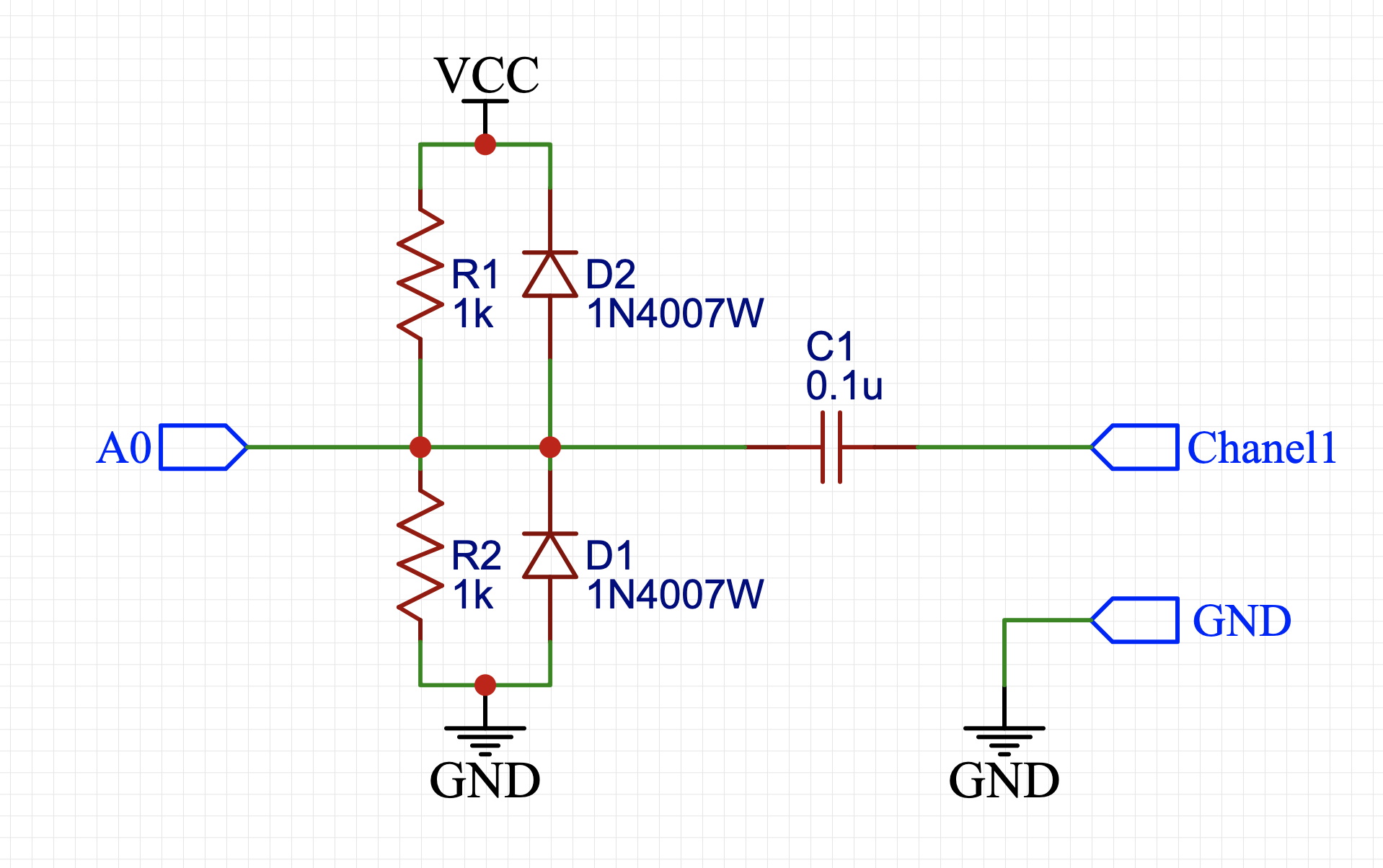
IngressCreated a simple stage with a capacitor and 2 resistors to keep the signal at 50% when idle, and sample signals between -1.65V and +1.65C. Also added 2 diodes to protect the inputs from over voltage. There is no amplification stage, in the future I can enable the internal OpAmp, with a range x2 - x16 amplification.
I used 2 of the 3 internal ADCs in 2 modes: Interleaved and dual channel.In interleaved mode, 2 ADC provides the samples alternatively to the DMA channel, to double the sampling speed. In Dual channel, I use 2 separated ADC and 2 different DMA channels, avoiding the complexity of mixing the data in a single buffer for 2 signals.
By only using DMA to fill in the buffer, the CPU is available to work on the visualization, indeed while the stm32 is refreshing the screen, the ADC is already filling in again the memory. To change the sampling speed, I act on the sampling period on the registry ADC1->SMPR1, variating from 1.9 micros to 250 micros per division (64 samples x division).At the highest speed 1.9 microsecond per division mean 29.6 nanosecond per sample, virtually 33 Mega Samples per second, but I had not any instrument to verify. As I was able to observe and measure via FFT a 12Mhz signal, it means i'm getting at least 24 Mega samples per seconds
The ADC setting is based on the STMSpeeduino library, I did some changes as was not working properly on the sampling rate required and on the DMA modes. While the CPU is busy displaying the signal and calculating the FFT, the ADC is preparing the next sample in DMA, to improve the refresh rate.
TriggerThere is no trigger to start the ADC sampling. Instead, the DMA collect 1024 samples and select the right point (lowest value) to start visualizing the following 512 samples. In this way, the display will be showing the waveform always in the same position, without keep the CPU busy awaiting to start the ADC.
OversamplingTo being able to sample slow signals while keep using the DMA in continuous mode, when oversampling is enabled, the DMA collect 10240 samples and afterward the data is analysed to get 1 sample as the average or 10 original samples. The STM32 provide oversampling via hardware, but I did not use on these tests.
FFTImplemented a simple FFT for two scopes: offer that visualization and estimate the frequency of the signal without using a counter. The estimation is done by identified the highest peak on the FFT domain and calculate the related frequency by knowing the sample rate. I used the library KickFFT, which calculate the FFT using integer, not float. While the precision is lower, te result is good enough for the scope.
By default, the FFT is off to improve the frame speed.
DisplayThe Arduino Giga Display shield offer 800 x 480 Pixels, big enough for a 512 x 256 pixel scope windows, and 512 x 192 FFT windows. The remaining space is used for some button for the touch screen, and a box showing the parameters, like Time x division, oversampling and frequency.The estimated frequency is displayed only when the FFT is on. As mentioned above, to avoid flickering refreshing the screen, I used sprites for both Scope and FFT box. When FFT or Oversampling (X10 on the button) are enabled, the respective button become green.
On X/Y mode, as expected, I use channel 1 (A0) for the X, and Channel 2 (A3) for Y, iterating on 512 samples starting from the trigger point
Not too much to add here.
void loop() {
/*  Check if ADC run is completed */
if (mode == 0) {
while (!TransferInterleavedComplete()) {}
} else {
while (!TransferSimultaneousComplete()){}
}
/*
Copy the full buffer or downsample
To free up the ADC buffer
*/

if (oversampling) {
downsampling();
} else {
copy_buffer();
}
/* Trigger again the ADC for the next 1024 samples */
recapture();


if ( mode < 2 ){
drawScope();    // Standard scope
} else {
drawXY();    // X/Y mode
}
/*  Calculate and visualize FFT only when enabled */
if (tfton) {
reset_fft();
prepare_samples();
calc_fft();
drawFFT();
}
/* Read imput from touch screen */
GetInput();Used two different sources: a cheap generator based on XR2206, and a second generator based on AD9833 controlled by my M5stack faces, using the rotary encoder to change the frequency in a very convenient way. This generator can achieve 12.5 MHz, which is exactly the max frequency I observed


Comments
Please log in or sign up to comment.