

_Mka4Nfm6gI.jpg?auto=compress%2Cformat&w=40&h=40&fit=min&dpr=2)
Hardware components | ||||||
 |
| × | 1 | |||
| × | 1 | ||||
 |
| × | 1 | |||
Software apps and online services | ||||||
 |
| |||||
 |
| |||||
One of the common used LED Tube driver chip is 74HC595, by using the Chip, you can save GPIO ports. I bought a LED Tube with 595 chip, it only need 3 GPIO ports to display 4 digits. However there is no existing posts about how to drive the 74HC595 LED Tube from Windows 10. So I can only try for myself.
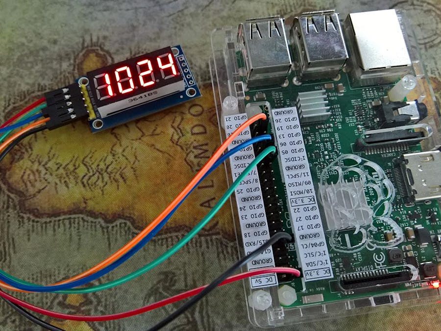
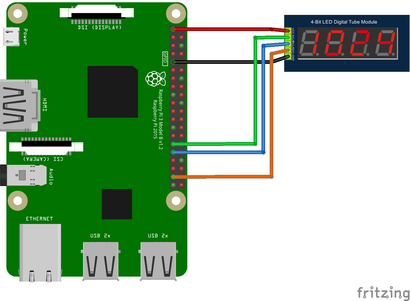
1. Physical Connection
VCC to DC3.3 power, GND to Ground, DIO to GPIO27 (you can change it, and change the program also). SCLK to gpio 5 (you can also change), RCLK to GPIO 06.
As shown below:
2. Coding
The shop give me a C++ code on Arduino:
/*******************************************************************************
* Software Author:	HQ
* Creation Date:        2015-2-10
* Software History:	2015-3-20
* Version:              2.0
* Sales address:       http://qifeidz.taobao.com/
********************************************************************************/
    unsigned char LED_0F[] =
    {// 0	 1	  2	   3	4	 5	  6	   7	8	 9	  A	   b	C    d	  E    F    -
    	0xC0,0xF9,0xA4,0xB0,0x99,0x92,0x82,0xF8,0x80,0x90,0x8C,0xBF,0xC6,0xA1,0x86,0xFF,0xbf
    };
    unsigned char LED[4];	//用于LED的4位显示缓存
    int SCLK = 2;
    int RCLK = 1;
    int DIO = 0; //这里定义了那三个脚
    void setup ()
    {
      pinMode(SCLK,OUTPUT);
      pinMode(RCLK,OUTPUT);
      pinMode(DIO,OUTPUT); //让三个脚都是输出状态
    }
    void loop()
    {
        LED[0]=1;
    	LED[1]=2;
    	LED[2]=3;
    	LED[3]=4;
    	while(1)
    	{
    		LED4_Display ();
    	}
    }
    void LED4_Display (void)
    {
    	unsigned char *led_table;          // 查表指针
    	unsigned char i;
    	//显示第1位
    	led_table = LED_0F + LED[0];
    	i = *led_table;
    	LED_OUT(i);
    	LED_OUT(0x01);
        digitalWrite(RCLK,LOW);
        digitalWrite(RCLK,HIGH);
    	//显示第2位
    	led_table = LED_0F + LED[1];
    	i = *led_table;
    	LED_OUT(i);
    	LED_OUT(0x02);
        digitalWrite(RCLK,LOW);
        digitalWrite(RCLK,HIGH);
    	//显示第3位
    	led_table = LED_0F + LED[2];
    	i = *led_table;
    	LED_OUT(i);
    	LED_OUT(0x04);
        digitalWrite(RCLK,LOW);
        digitalWrite(RCLK,HIGH);
    	//显示第4位
    	led_table = LED_0F + LED[3];
    	i = *led_table;
    	LED_OUT(i);
    	LED_OUT(0x08);
        digitalWrite(RCLK,LOW);
        digitalWrite(RCLK,HIGH);
    }
    void LED_OUT(unsigned char X)
    {
    	unsigned char i;
    	for(i=8;i>=1;i--)
    	{
    		if (X&0x80)
                {
                  digitalWrite(DIO,HIGH);
                 }
                else
                {
                  digitalWrite(DIO,LOW);
                }
    		X<<=1;
                digitalWrite(SCLK,LOW);
                digitalWrite(SCLK,HIGH);
    	}
    }
We only need to display Numbers. So we only need 0-9 from the LED_0F array, the C# definition is this:
byte[] LEDDIGITS =
{
    // 0    1    2    3    4	5	 6	  7	   8    9
    0xC0,0xF9,0xA4,0xB0,0x99,0x92,0x82,0xF8,0x80,0x90
};
GPIO Pins
public GpioPin PinDIO { get; set; }     // Serial Digital Input
public GpioPin PinRCLK { get; set; }   // Register Clock
public GpioPin PinSCLK { get; set; }   // Serial Clock
Initiate GPIO Controller and Pins.
public LED74HC595Driver(int dioPin, int rclkPin, int sclkPin)
{
    var gpio = GpioController.GetDefault();
    // setup the pins
    PinDIO = gpio.OpenPin(dioPin);
    PinDIO.SetDriveMode(GpioPinDriveMode.Output);
    PinRCLK = gpio.OpenPin(rclkPin);
    PinRCLK.SetDriveMode(GpioPinDriveMode.Output);
    PinSCLK = gpio.OpenPin(sclkPin);
    PinSCLK.SetDriveMode(GpioPinDriveMode.Output);
    // initialize the pins to low
    PinDIO.Write(GpioPinValue.Low);
    PinRCLK.Write(GpioPinValue.Low);
    PinSCLK.Write(GpioPinValue.Low);
}
C# translation of "void LED_OUT(unsigned char X)"
// Serial-In-Parallel-Out
void WriteSIPO(byte b)
{
    for (int i = 8; i >= 1; i--)
    {
        PinDIO.Write((b & 0x80) > 0 ? GpioPinValue.High : GpioPinValue.Low);
        b <<= 1;
        PulseSCLK();
    }
}
In order to use, add 2 helper methods
// Pulse Register Clock
void PulseRCLK()
{
    PinRCLK.Write(GpioPinValue.Low);
    PinRCLK.Write(GpioPinValue.High);
}
// Pulse Serial Clock
void PulseSCLK()
{
    PinSCLK.Write(GpioPinValue.Low);
    PinSCLK.Write(GpioPinValue.High);
}
Now we can refact the logic of "void LED4_Display (void)". Create a new method, to display a single number on a particular tube.
public void DisplayChar(int index, byte b)
{
    if (index < 0 || index > 3)
    {
        throw new ArgumentOutOfRangeException(nameof(index), "index just be between 0-3.");
    }
    int i = 0x01;
    i = i << index;
    WriteSIPO(b);
    WriteSIPO((byte)i);
    PulseRCLK();
}
The index stands for different tubes from right to left. 0 is the 1st tube, 2 is the second, 3 is the third, 4 is the last. Because it is 4 digits, it can not excceed 9999, so remember to check the range. I didn't consider the nagetive numbers, so it will be 0-9999.
For example, you want to display "8" on the second tube, like _ _ 8 _
DisplayChar(1, 0x80)
the number "8" is already defined in LEDDIGITS.
In order to be easy to use, write a method, take int type number, then convert to byte to display.
public void DisplayDigits(int number)
{
    if (number < 0 || number > 9999)
    {
        throw new ArgumentOutOfRangeException(nameof(number), "number must be between 0-9999");
    }
    // 老司机写法
    var numStr = number.ToString();
    for (int i = 0; i < numStr.Length; i++)
    {
        var pos = numStr[numStr.Length - i - 1] - '0';
        DisplayChar(i, LEDDIGITS[pos]);
    }
    // 新司机写法
    //// 个位
    //var ge = number % 10;
    //// 十位
    //var shi = number / 10 % 10;
    //// 百位
    //var bai = number / 100 % 10;
    //// 千位
    //var qian = number / 1000 % 10;
    //DisplayChar(0, LEDDIGITS[ge]);
    //DisplayChar(1, LEDDIGITS[shi]);
    //DisplayChar(2, LEDDIGITS[bai]);
    //DisplayChar(3, LEDDIGITS[qian]);
}
Then is the difficult part. How the LED Tube works is, by refreshing the characters on each tube for a very fast rate, human eye can not see the refresh, it will show like there are 4 digits at the same time. So that's why there are a while(1) loop in that C++ code.
Translating to C#, in UWP, you will need a background worker so your app start page don't stuck.
public sealed partial class MainPage : Page
{
    public LED74HC595Driver Led74Hc595Driver { get; set; }
    public MainPage()
    {
        InitializeComponent();
        Led74Hc595Driver = new LED74HC595Driver(26, 6, 5);
        BackgroundWorker worker = new BackgroundWorker { WorkerSupportsCancellation = true };
        worker.DoWork += (sender, args) =>
        {
            while (true)
            {
                Led74Hc595Driver.DisplayDigits(1024);
            }
        };
        Loaded += (sender, args) =>
        {
            worker.RunWorkerAsync();
        };
    }
}
Finally, the complete code:
using System;
using System.Collections.Generic;
using System.Linq;
using System.Text;
using System.Threading.Tasks;
using Windows.Devices.Gpio;
namespace LEDTube74HC595
{
    public class LED74HC595Driver
    {
        byte[] LEDDIGITS =
        {
            // 0    1    2    3    4	5	 6	  7	   8    9
    	    0xC0,0xF9,0xA4,0xB0,0x99,0x92,0x82,0xF8,0x80,0x90
        };
        private byte[] LEDCHARS =
        {
            // A     b     C     d     E     F     -
            0x8C, 0xBF, 0xC6, 0xA1, 0x86, 0xFF, 0xbf
        };
        public GpioPin PinDIO { get; set; }     // Serial Digital Input
        public GpioPin PinRCLK { get; set; }   // Register Clock
        public GpioPin PinSCLK { get; set; }   // Serial Clock
        public LED74HC595Driver(int dioPin, int rclkPin, int sclkPin)
        {
            var gpio = GpioController.GetDefault();
            // setup the pins
            PinDIO = gpio.OpenPin(dioPin);
            PinDIO.SetDriveMode(GpioPinDriveMode.Output);
            PinRCLK = gpio.OpenPin(rclkPin);
            PinRCLK.SetDriveMode(GpioPinDriveMode.Output);
            PinSCLK = gpio.OpenPin(sclkPin);
            PinSCLK.SetDriveMode(GpioPinDriveMode.Output);
            // initialize the pins to low
            PinDIO.Write(GpioPinValue.Low);
            PinRCLK.Write(GpioPinValue.Low);
            PinSCLK.Write(GpioPinValue.Low);
        }
        public void DisplayChar(int index, byte b)
        {
            if (index < 0 || index > 3)
            {
                throw new ArgumentOutOfRangeException(nameof(index), "index just be between 0-3.");
            }
            int i = 0x01;
            i = i << index;
            WriteSIPO(b);
            WriteSIPO((byte)i);
            PulseRCLK();
        }
        public void DisplayDigits(int number)
        {
            if (number < 0 || number > 9999)
            {
                throw new ArgumentOutOfRangeException(nameof(number), "number must be between 0-9999");
            }
            // 老司机写法
            var numStr = number.ToString();
            for (int i = 0; i < numStr.Length; i++)
            {
                var pos = numStr[numStr.Length - i - 1] - '0';
                DisplayChar(i, LEDDIGITS[pos]);
            }
            // 新司机写法
            //// 个位
            //var ge = number % 10;
            //// 十位
            //var shi = number / 10 % 10;
            //// 百位
            //var bai = number / 100 % 10;
            //// 千位
            //var qian = number / 1000 % 10;
            //DisplayChar(0, LEDDIGITS[ge]);
            //DisplayChar(1, LEDDIGITS[shi]);
            //DisplayChar(2, LEDDIGITS[bai]);
            //DisplayChar(3, LEDDIGITS[qian]);
        }
        // Serial-In-Parallel-Out
        void WriteSIPO(byte b)
        {
            for (int i = 8; i >= 1; i--)
            {
                PinDIO.Write((b & 0x80) > 0 ? GpioPinValue.High : GpioPinValue.Low);
                b <<= 1;
                PulseSCLK();
            }
        }
        // Pulse Register Clock
        void PulseRCLK()
        {
            PinRCLK.Write(GpioPinValue.Low);
            PinRCLK.Write(GpioPinValue.High);
        }
        // Pulse Serial Clock
        void PulseSCLK()
        {
            PinSCLK.Write(GpioPinValue.Low);
            PinSCLK.Write(GpioPinValue.High);
        }
    }
}
Run:
_Mka4Nfm6gI.jpg?auto=compress%2Cformat&w=60&h=60&fit=min&dpr=2)


Comments
Please log in or sign up to comment.