EE-Emerge is a course offered by the University of California, Davis for sophomores and juniors who have an interest in computer science, electrical engineering, and computer engineering. Throughout a year, students organize and manage a yearlong electronic project. None of this is possible without Texas Instruments' sponsorship.
Hardware Team
- Aiseosa Omorogieva
- Anelise Cho
- Anthony Pham
- Devon Liu
- Jan Truong
- Jeff Chhen
- Varsha Senthil
Firmware Team
- Anelise Cho
- Anthony Pham
- Gisselle Ibarra
- Jan Truong
- Jeff Chhen
- Scott Ballinger
- Varsha Senthil
- Victoria Pierce
EasyBreathe provides an electronic-based face mask designed for medical workers that is comfortable and conscientious to use. The EasyBreathe mask utilizes a centrifugal fan to provide airflow to the user's mask. An optimized human machine interface is also used to allow intuitive operation and status reporting for a user. The developed mask allows medical workers to work more comfortably and makes working easier through its communication features.
Hardware + Firmware DesignHere is the journey that we took to get to our current design iteration. The entire EasyBreathe team (Mechanical, Hardware, Firmware) collaborated to establish the Top-Level Diagram to construct and determine the core functionality of the electronic mask.
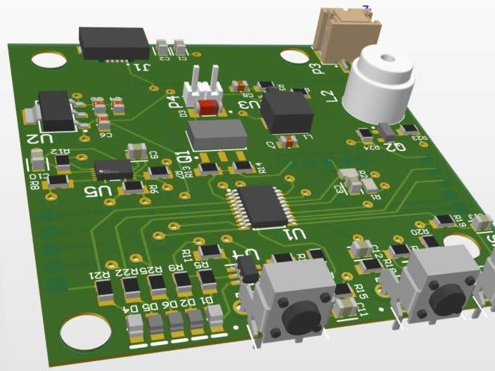
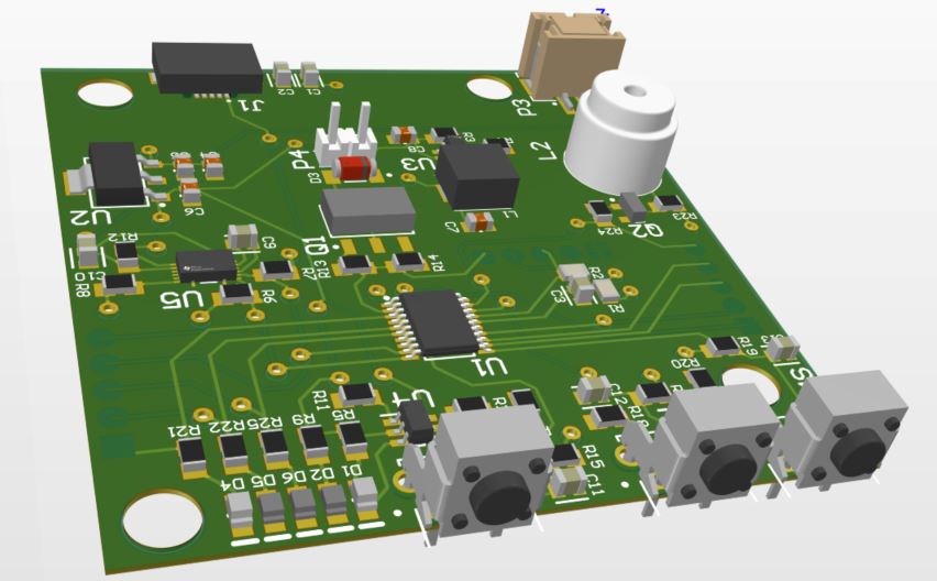
Based on the top-level diagram, the goal of the hardware design was to power the fan, battery, control buttons, and indicator LEDs. Two buttons are for controlling fan speed and a third is for checking battery life. The LEDs indicate to the user how much battery is left. Components were chosen based on availability through our chosen manufacturer, JLCpcb. By having a third-party manufacture the PCB, human error is reduced and more time is left for testing and validation.
Microcontroller (1/4)
- The MSP430G225 was chosen because it offered Low Power Mode, I2C Communication, and met our IO Port requirement (16). 8 IO Ports were used for User Interface, while the remaining were used for testing and communication. The MSP430 met our price point which will keep our product affordable and readily available.
Battery Control (2/4)
- Fuel gauge circuit: determines how much charge remains in the battery by measuring the current flowing through a small resistance resistor, R30. I2C communication protocol is used to communicate with the Microcontroller. Pull-up resistors are used to drive I2C pins high, allowing the Microcontroller to pull the SDA line down when it requests information.
Power Supply (3/4)
- Linear Voltage Regulator (LDO): steps down 3.7V battery voltage to 3.3V to power MCU
Motor Control (4/4)
- The motor control circuit controls fan speed through pulse width modulation (PWM). This determines how long the MOSFET remains on and off. A higher duty cycle results in a faster fan.
Standard C++ was used in combination with Arduino’s own C++ language. I2C Communication Protocol was used between the microcontroller and fuel gauge. Texas Instruments Cloud Composer Studio was used to design and test the software.
A notable feature in the software is the conservation of power by utilizing hardware interrupts. Rather than the program constantly checking if the increasing and decreasing speed buttons are pressed, a hardware interrupt executes an action (in this case, changing fan speed) only when requested by a button push.
The HMI consists of 3 switch buttons, 3 LED’s and a Piezo Buzzer. Two buttons can be used to adjust the fan speed, while the third is used to check the battery level. The LED’s display battery information and the piezo buzzer is used to alert the user of low battery levels.
Battery Display
- Upon a user pressing the battery state button, 3 LEDs display the battery state of charge reported by a fuel gauge through 3 states: solid, blinking, or off. When the battery charge falls below 15%, the user is notified by a flashing LED along with an audible buzzer.
Fan Logic & Control
- Fan Speed is controlled through two buttons: Fan Speed Up, and Fan Speed Down.
- The fan speed is controlled using PWM. A higher duty cycle means a faster fan speed, while the opposite holds true for a lower duty cycle. The Speed Up button increases the duty cycle, while the Fan Speed Down button lowers the duty cycle.
Originally, we worked with the firmware team to ensure certain functionality implementations were actuated, such as buttons and LEDs for the user interface. The schematics for determined fan functionalities were created. The PCB board has a 1-in by 3-in dimension in hopes to create a product that is portable and lightweight.
In the next iteration, we made changes to enhance the user experience. This was done by moving buttons to a common side. Through-hole LEDs were considered at this stage as a means to increase light visibility.
For the third and current iteration, the Hardware Team worked alongside the Mechanical Design team to determine optional dimensions and LED and button placements to better enhance functionality while still being conservative with space. The two teams determined that the best PCB dimension would match the dimension of the fan chosen for the electric mask. LEDs and buttons were moved to the top of the PCB so that a user wearing the fan box on their waist will have better and easier access.
Component placement and mounting was decided in conjunction with the mechanical team. Component selection was done with consideration of availability and whether they were available through our PCB manufacture, JLCpcb. This saves time in the production process and allows for more testing and validation.
Current Hardware Revision efforts are spent with the Mechanical team in optimizing the layout of our design dimensions, button layout, and power management. Depending on user feedback, iterations will be made in regards to comfort, useability, and power consumption.
Future firmware iterations are to further enhance the software to prolong battery life by utilizing low power modes offered by the MSP430. Additional software support for future hardware implementations will be developed to ensure the reliability of the system.


Comments
Please log in or sign up to comment.