


Software apps and online services | ||||||
 |
| |||||
*******
Please visit https://proteshea.com/led-bar-graph-and-keypad-with-arduino-uno/ for a complete list of materials needed for this project.
*******
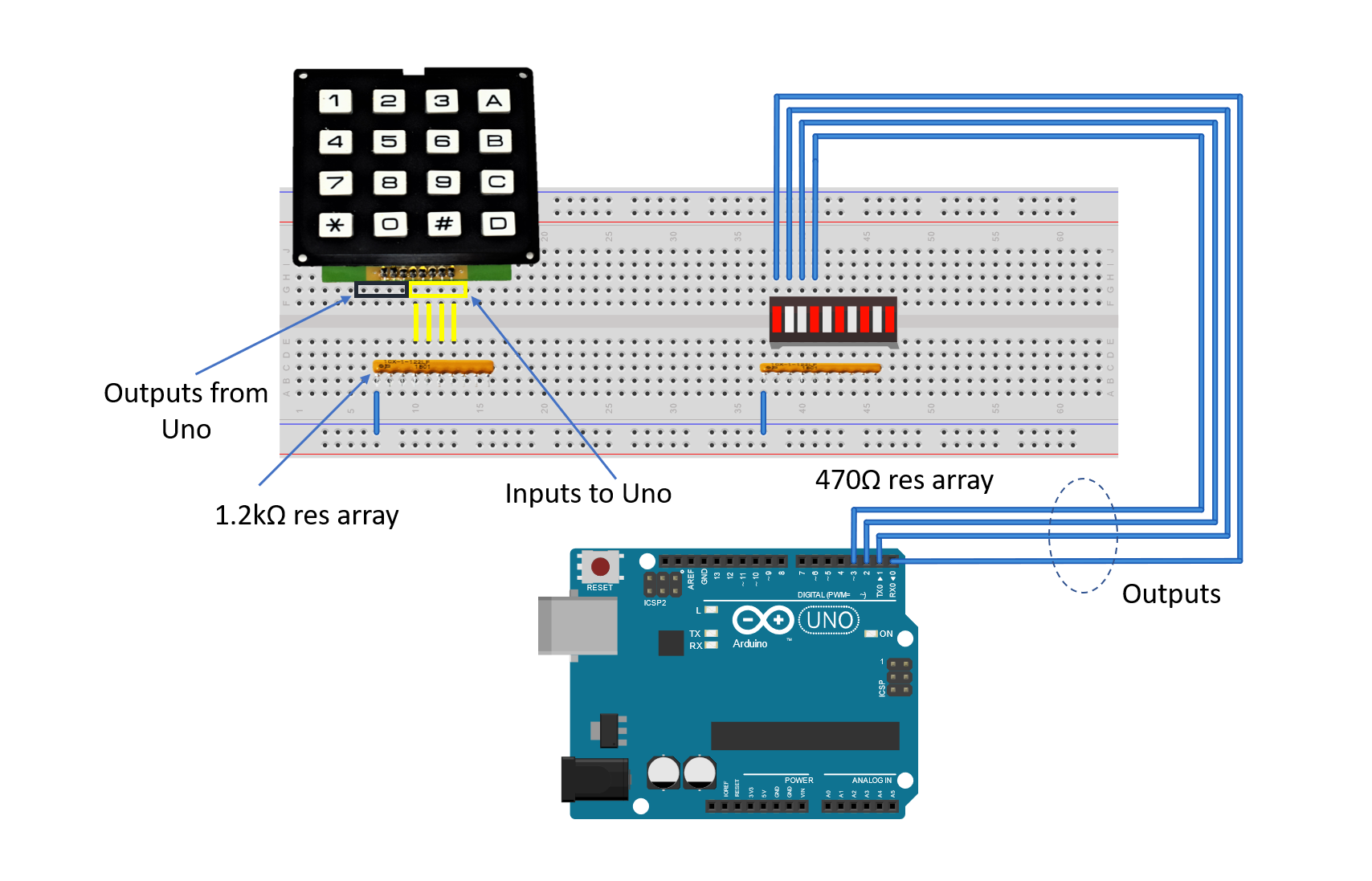
IntroductionIf you haven’t read our Getting Started Guide or Project 1 for the Arduino Uno Rev3 (Uno), please read those first. Otherwise, continue reading. In this tutorial, we’ll be swapping out the switch array from Project 1, to a 16-key matrix keypad. Instead of using 9/10 of the LEDs, we’ll be using only 4/10. Again, each LED input will be an output from the Uno and each keypad output will be an input to the Uno. We also need four outputs from the Uno to drive the four columns of the keypad. In total, we’ll need 8 digital outputs and 4 digital inputs on the Uno.
LED Bar GraphPlease see Arduino Uno Rev3 Project 1 to learn more about the LED Bar Graph and how to wire the 470 ohm resistor array in series with each LED.
16-Key Matrix KeypadThe keypad consists of 16 keys with numbers 0-9, letters A-D, an asterisk, and a pound symbol. The keypad consists of 4 columns and 4 rows. We will drive the 4 columns and read the 4 rows to determine what key is pressed. The layout and internal circuitry of the keypad is below. The pinout may vary, but this is how the pins are marked on my keypad.
To determine if a key is pressed, we first have to cycle each column high in sequential order, then check to see if each row output went high. For example, we’ll set column 1 high, then check if keys 1, 4, 7, or * is pressed. Once that check is done, we set column 1 low, then set column 2 high. When column 2 is high, we check if 2, 5, 8, and 0 is pressed, and so on.
Each row will be connected to a pull-down resistor, so when the key is not pressed, the Uno will read 0V on its input. When the key is pressed, +5V gets routed to the Uno’s input. For example, when column 1 is high, key 1 gets pressed, and +5V will get routed to row 5. A video is shown below to show what happens.
I’m using a breadboard instead of Modulus since almost everybody has a breadboard. First, let’s place the LED bar graph and keypad onto the breadboard. Insert the bar graph so that the body is over the valley of the breadboard. You do not want the pins to short each other by being connected to the same node. Next, place the 470 ohm resistor array on the cathodeside of the LED and tie pin 1 of the array to GND. Make sure that pin 1 of the resistor array is not connected to any of the cathodes of the LED bar graph. By plugging in the resistor array, you now have a resistor connected in series with each of the four LEDs.
Next, use a M/M jumper to wire the anode side of the LED bar graph as outputs to the Uno pins 8-11. For example, pin 7 of the bar graph will get wired to Uno pin 8, pin 8 of the LED will get wired to Uno pin 9, and so on.
Place the 1.2k ohm resistor array as shown in the image below. Tie pin 1 of the array to GND, and make sure it does not connect to any of the pins on the keypad. The breadboard holes outlined in blue-grey will be tied to Uno pins 0-3. For example, pin 1 (column 1) on the keypad will be wired to pin 0, pin 2 (column 2) on the keypad will get wired to pin 1, and so on. The breadboard holes outlined in yellow get routed to Uno pins 4-7. For example, pin 5 (row 1) on the keypad will be wired to pin 4, pin 6 (row 2) on the keypad will get wired to pin 5, and so on.
If you haven’t mounted the Uno onto the prototyping area of the FuelCan, go ahead and do that. I placed the breadboard in the bottom storage compartment to limit the length of the jumper wires. We need to supply +5V and GND to the power and ground rails on the breadboard. Use the provided banana jack to test-lead clip cables to do so. You will need two male header pins to mount the test-lead clips to on the breadboard side. Plug the Type A side of the USB cable into the USB1 receptacle and the Type B side into the Uno’s receptacle. Power up the FuelCan with the AC-DC power adapter.
SoftwareOnce the wiring is complete and the FuelCan is powered up, we can now load the sketch onto the Uno. The sketch is below. The table below shows how we mapped each key to a binary number.

Comments
Please log in or sign up to comment.