Smoking is extremely hazardous to health. Even in the smoking areas, people intend to smoke. This passive smoke is unhealthy for other surrounding people. That’s why I have developed a smoke detector for no-smoking zones. A pair of these devices can be installed in the no-smoking zones of hotels, hospitals, malls, etc.
Working of the circuit: The working of the circuit is pretty simple. When the MQ-2 gas sensor senses smoke and the value of the smoke goes beyond 150, the Arduino will be signaled to buzz the buzzer and a cross will appear on the Matrix dot display. So, when a person starts smoking in a no-smoking zone, the surrounding people will be alarmed.
First of all, we need to learn in detail about each component and the working of the circuit. Components are as follows:
1) MQ-2 Gas sensor: MQ2 gas sensor is an electronic sensor used for detecting the concentration of gases in the air. This sensor contains a sensing material whose resistance changes when it comes in contact with the gas. This change in the value of resistance is used for the detection of gas. It has four pins namely, Gnd, Vcc, AO (Analog output), and DO (Digital Output). The pinout diagram of this sensor is shown below.
Note: In this project, I am using an 8x8 matrix display module (MAX7219).
2) Matrix dot display (MAX7219): A matrix dot display is an electronic device that uses a patterned led array to display numbers, alphabets, graphics, etc. The display has five pins CLK, CS, DIN, GND, and Vcc. The pinout diagram of the MAX719 is given below.
There is a total of 64 LEDs in an 8X8 dot matrix display. A typical 8×8 dot matrix unit has 16 pins, 8 for each column and 8 for each row. By, wiring the rows and columns together the number of pins is reduced to 16. If they were not wired, there would be a total 65 number of pins ( one for one led each and one for a common anode or cathode connector). The pattern of LEDs on the matrix dot display is given below:
3) Buzzer: Buzzer is an audio signaling device that is commonly used as an output. It has two pins namely, negative and positive.
4) Arduino UNO is a micro-controller based on Chip ATmega328p. It has 14 digital pins, six analog pins, 16 MHz ceramic resonators, a USB connection, a power jack, an ICSP header, and a reset button. It can be powered using a tablet, laptop, mobile through a USB cable, or using an external battery. Arduino UNO is programmed using the software Arduino IDE.
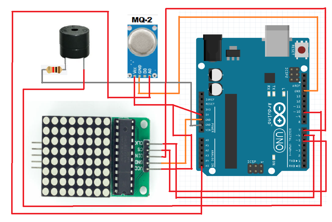
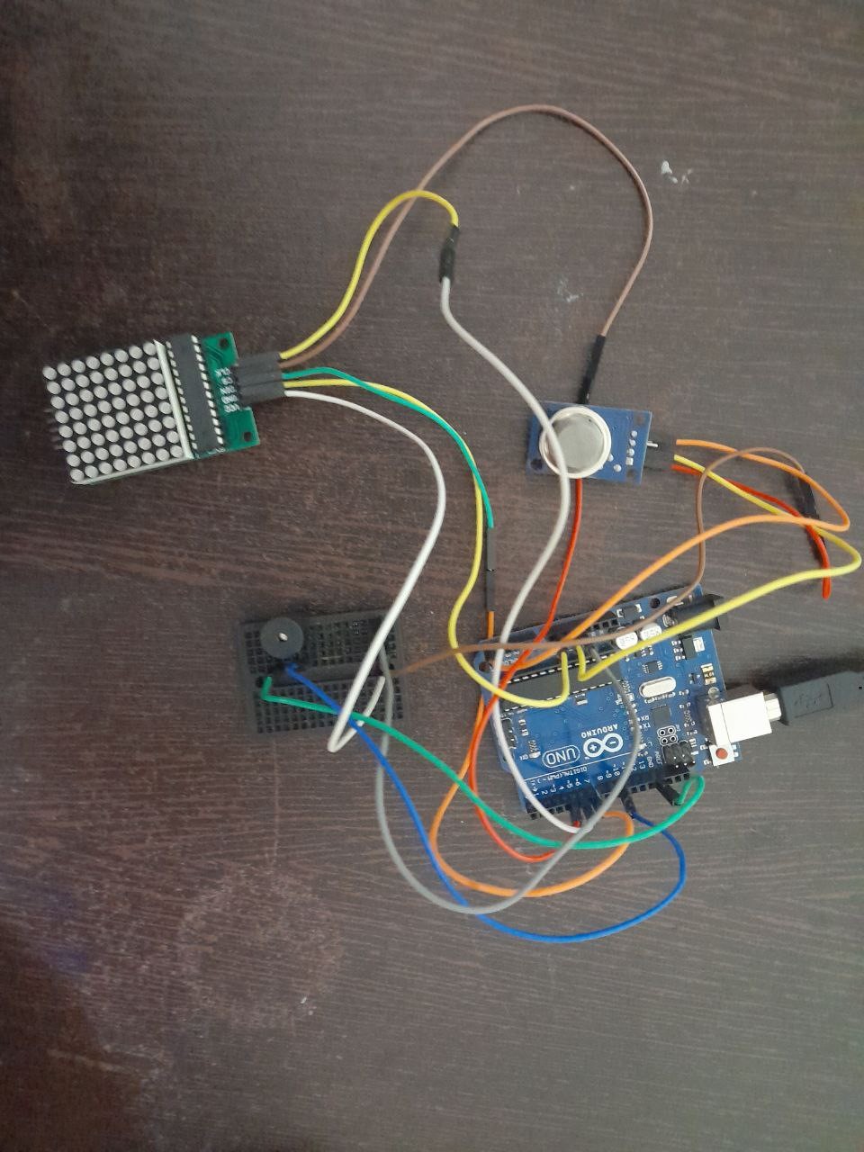
Now, let's get started with assembling the circuit. The connections are as follows:
The circuit diagram is given below:
Now, let's start coding !!!
A basic Arduino code has two parts; void loop and void setup. The void setup is only run once. The void loop contains the main code and is run again and again. The code for the circuit is given below. Before, uploading the code to the software, download the libraries of Matrix dot display (MAX7219). The Ledcontrol and MaxMatrix libraries are two of the most common libraries for Matrix display. In the project, we will be using the Mat Matrix library. For downloading the libraries, simply go to the Tools option in the IDE software.
In the tools section, there is an option called "Manage libraries". After clicking on manage libraries there is a search section. There you can search for the MatMatrix library and install it.
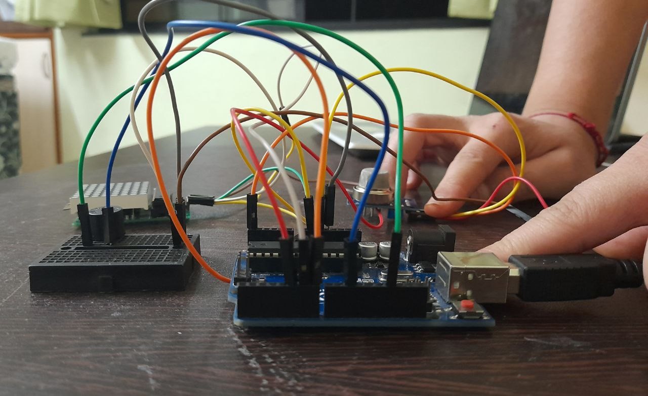
Results-: After uploading the code, check the values on the serial monitor. You will see that when there is no smoke around the MQ-2 Gas sensor the values will be below 150. And once, there is smoke around the sensor the values will go beyond and the buzzer will buzz and a cross will appear on the matrix dot display.


_ztBMuBhMHo.jpg?auto=compress%2Cformat&w=48&h=48&fit=fill&bg=ffffff)


Comments
Please log in or sign up to comment.