What are we making here?
In this hackster tutorial, I will show you how to create a simple cloud-connected multi-point star network that will be comprised of multiple sub-1GHz RF sensor nodes.
Each sensor node will read an analog sensor (i.e. ambient light, moisture, potentiometer), encode the data into JSON, then send the JSON-encoded payload to a Wi-Fi enabled hub.
The hub will be a sub-1GHz-to-Wi-Fi gateway. It will be able to aggregate all of the sensor data coming from the various sub-1GHz nodes. Each JSON payload it receives, the hub will simply forward the data up to the cloud using MQTT over Wi-Fi.
Why Sub-GHz?
Sub-1GHz is a great wireless technology for home automation. This is because sub-1GHz has several benefits over its 2.4GHz cousins (i.e. Wi-Fi, bluetooth, BLE, etc). Sub-1GHz radios have the benefit of being lower power, can enable farther range (up to several kilometers with line of sight!), and can permeate through walls much better than 2.4GHz radios.
In the setup that we are building, we'll be able to have "whole-house" coverage with our sensor network, allowing us to deploy our sensor nodes throughout a home or office setting.
Let's make a sub-1GHz RF sensor node!!
THE HARDWARE
We are using the Texas Instruments LaunchPad development kits for our system. To make our sensor node, we will use:
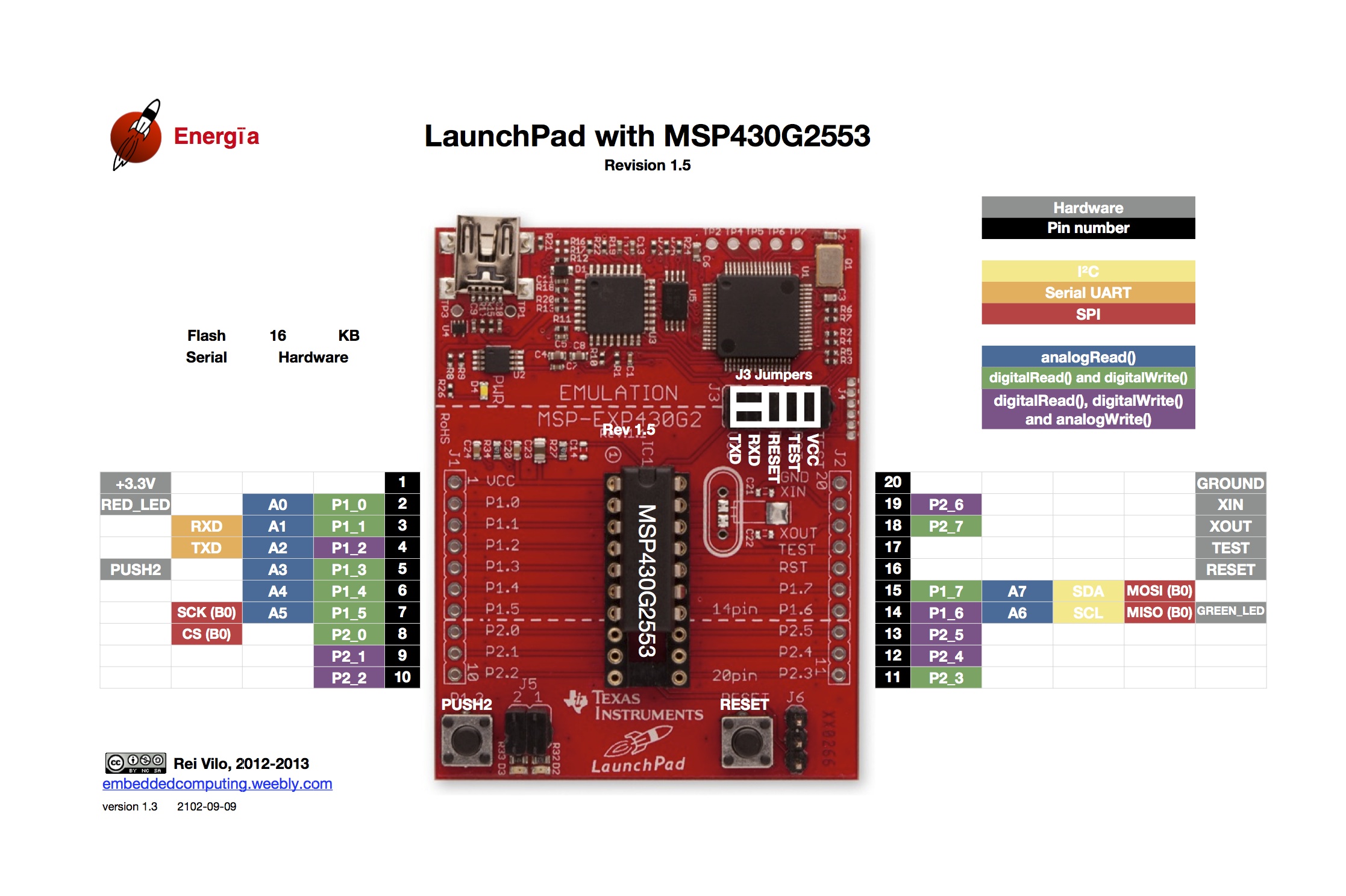
- MSP-EXP430G2 LaunchPad (however, almost any LaunchPad kit would do)
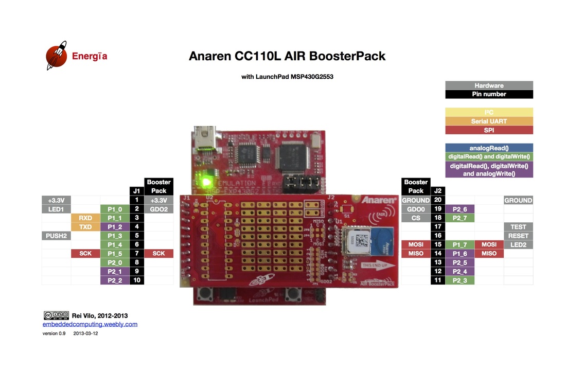
- 430BOOST-CC110L SubGHz RF Radio
- Analog sensor from Seeed Studio (i.e. moisture, potentiometer, ambient light)
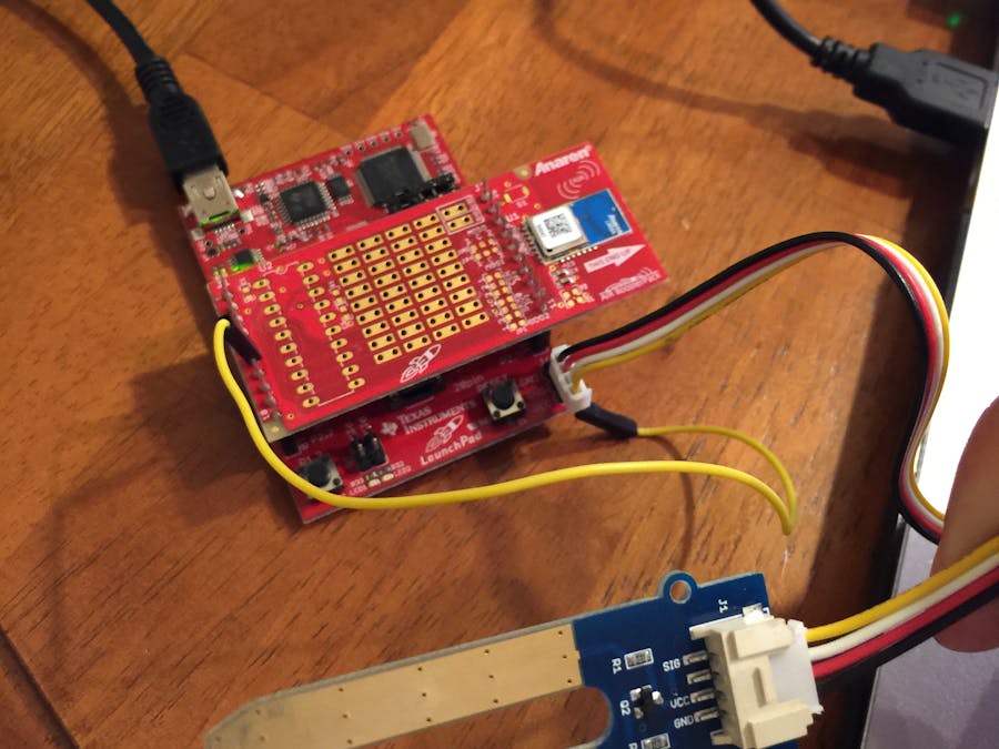
Thanks to the modularity of the LaunchPad/BoosterPack, setting up the hardware is easy. Simply plug in the LaunchPad & CC110L RF BoosterPack together as shown in the picture below.
To connect the Grove sensor, I connected the 3 pins as follows:
- VCC/Power pin (Red wire) >> 3v3 pin of the LaunchPad
- Grove GND pin (Black wire) >> GND pin of the LaunchPad
- Signal pin (Yellow wire) >> pin 6 of the LaunchPad
[NOTE] If using the MSP-EXP430G2 LaunchPad, be sure that the UART jumpers (J3) of the LaunchPad are configured for "HW UART". This is done by rotating the 2 left-most jumpers 90degrees so that they are "horizontal".
THE SOFTWARE!
Now that our hardware is all set up, we can program our LaunchPad! We are using Energia. Energia is an open source software development tool for the TI LaunchPad development kits. Energia is based on the Arduino & Wiring frameworks, so many libraries & example code you may already be familiar with will work on the LaunchPad kits.
You can use the Energia IDE, or TI's cloud-based IDE, called CCS Cloud to do your firmware development.
The code is available below in the "Code section" of this hackster tutorial.
Here is a quick overview of the code:
SETUP:
- Start the radio using the Radio.begin() API. This will configure our CC110L Sub-GHz RF radio BoosterPack.
- Next, we use memset() to reserve some memory for the JSON-encoded payload that we will send out over the radio
- Next, we use the Serial.begin() API to configure our Serial port/UART. This will allow us to send data back to the PC.
- Then, we configure our GPIO pin as output for our on-board RED LED of the LaunchPad. We'll use this to blink whenever we transmit new data over the RF radio.
LOOP:
- First thing we do in loop is turn the RED LED on. This will signify that we are starting a RF transmit!
- Next, we read our analog sensor using the analogRead() API.
- Next, we format our JSON payload. Our JSON payload will look like this: {"Adrian": {"Water" : 123}}
- This way anyone who receives this data will know where it came form (i.e. Adrian), the type of sensor data it is (i.e. Water/moisture), and the data reading (i.e. 123)
- Once our data is encoded into a JSON string, we need to typecast it to a char array because that is what our Radio.transmit() API requires
- We can finally send our data over subGHz RF radio using the Radio.transmit() API!
- Next, we'll print the JSON-encoded payload and send it out to the terminal using the Serial.println() API. This way we can see the latest JSON-encoded payload in a serial monitor.
- Lastly, we turn off the RED LED to signify that our RF transmit is complete
- Delay until the next reading. We can change the frequency of our transmits by changing the delay value.
MODIFICATIONS TO THE CODE:
For the most part, you shouldn't have to change this code too much. There are really only a few areas that you may want to edit:
- String myName = <YOUR INITIALS>; // This will be added to the JSON payload (default: AMF)
- String mySensor = <SENSOR TYPE>; // What type of sensor are you using? (default: Water/moisture)
- delay(TIME); // Change time to alter the frequency of transmissions
Let's make a Wi-Fi connected hub (IoT Gateway)!
THE HARDWARE
Again, we will be using the CC110L RF BoosterPack. However, this time we will use the CC3200-LAUNCHXL Wi-Fi LaunchPad. By pairing these 2 boards together, we'll be able to communicate over subGHz RF with the CC110L radio as well as over Wi-Fi with the CC3200 radio.
Just as before, simply plug in the CC110L RF BoosterPack into the CC3200 Wi-Fi LaunchPad as shown in the image below.
THE SOFTWARE
We will again use Energia to program the CC3200 Wi-Fi LaunchPad to act as our Sub-GHz RF-to-Wi-Fi gateway. To create this project, we used several Energia code examples, including WirelessTest (from the AIR430BOOST_FCC library that was written for the CC110L) and the MQTTBasicWiFi example (from the PubSubClient library that was written for the CC3200 Wi-Fi BoosterPack). The code is available below in the "code section" of this hackster tutorial.
Here is a quick overview of the code:
SETUP
- Like we did in the sensor node example, we use the Radio.begin() API to configure the CC110L RF Radio BoosterPack
- Next, we use the Serial.begin() API to configure our Serial port/UART
- Next, we use the WiFi.begin() API to connect our CC3200 WiFi LaunchPad to our Wi-Fi network
- Once connected, we call a function called printWiFiStatus(), which prints out some details of the Wi-Fi network that we just connected to.
- Next, we use the memset() API to reserve some memory for the incoming JSON-encoded payloads that we expect to receive from the various sensor nodes.
- We then configure our RED LED of the LaunchPad as an output and initialize to off. We will blink this LED every time we receive a new payload.
LOOP:
- First thing we do in the loop function is check to see if we're connected to an MQTT broker using the client.connected() API. This returns a boolean (true/false).
- If we're not connected, we can use the client.connect() API to connect to an MQTT broker. In this example, we're using a public MQTT Broker (iot.eclipse.org:1883)
- Once connected, we use the Radio.receiverOn() API, which uses the CC110L to check if there are any incoming packets coming in over SubGHz.
- If data is available, we turn the RED LED on, the print out the incoming message onto the Serial Monitor.
- We then forward the incoming payload to the cloud over MQTT using the client.publish() API. This API will publish the JSON-encoded message that we just received over SubGHz RF radio to a specific MQTT topic ("mySensorData").
- Once we publish our payload to the cloud, we turn the RED LED OFF.
- That's it in loop! We just loop here over and over again checking to see if the CC110L RF radio receives any new packets. If so, forward them up to the cloud over MQTT!
MODIFICATIONS TO THE CODE:
Again, this code can remain mostly unchanged. There are a few things that you may want to edit:
- char ssid[] = <YOUR WIFI NETWORK NAME>; // Enter your Wi-Fi credentials here!
- char password[] = <Your WIFI PASSWORD>;
- char server[] = <URL to your MQTT Broker>; // Default: iot.eclipse.org
- client.connect(<CLIENT NAME>); // Put a unique name for your hardware. This should be unique to ensure there are no other MQTT clients connecting to the MQTT broker with the same client name.
- client.pubish(<TOPIC>, (char*)rxPacket.message); // Change TOPIC to a unique topic that you can subscribe to.
NOW YOU CAN SUBSCRIBE TO YOUR SUB-GHZ RF SENSOR NODE!
That's it! Now use your favorite MQTT client to subscribe to your various sensor nodes. You can add additional subGHz RF sensor nodes to this network. Give each sensor node a unique name so that you can uniquely identify them when you receive the incoming MQTT payloads.


Comments
Please log in or sign up to comment.