


Hardware components | ||||||
 |
| × | 1 | |||
| × | 1 | ||||
| × | 1 | ||||
| × | 1 | ||||
| × | 1 | ||||
| × | 1 | ||||
Update:
I made a clearer video showing the complete functionality of Fishy Machine. I was doing some changes on the software and set the feeding interval to 3 seconds just to film the video. Normally I have it set to 24 hours, I would like to add a screen and some UI possibilities on V2 (if it ever comes to fruition).
Complete Fishy Machine Video
The Problem
I have a fish who is like all fish - pretty stupid. When you give him too much food, he will eat himself to death. Existing automatic feeding devices do not have great portion control. Therefore I decided to build one which could provide a defined portion at set intervals for when I went on holidays (I hate asking my neighbors).
Requirements
1. Portion control
2. Controlable feeding interval
3. Embedded design for easy plug and play use (no configuration)
4. Flexible power supply options (14-20v).
5. Indication LEDs and switches for basic control.
6. On board reprogramming using Launchpad as programming interface
Hardware
MSP430 for the uC.
L293NE for the stepper driver.
Balluff BES 516-375-S4-C (inductive proximity switch) for home operation.
LM-319 Stepper motor (salvaged from old printer)
RC Car axle coupler for the interface to the carrier.
Custom made chassis + carrier mechanism using a M3 threaded rod and some aluminium bits for the sliding surfaces.
Construction
Here is the schematic (I used Fritzing, I don't recommend it):
Here is a breakdown of each block of the schematic.
1. Control Switches
There are three switches which are active high or low depending on how you populate the PCB. The reason for this is: OSHpark requires a minimum order quantity of 3 boards and I would like to use the other two boards for some other projects.
The Home which runs the carrier toward the motor until the proximity sensor detects it and then it will reverse and line up the first feeding hole.
The Reset switch resets the uC.
The Start switch starts the feeding cycle after the home routine is validated.
Nothing really exciting here, a few decoupling caps for the uC, and a voltage divider for the output of the limit switch which has a 12V output.
I am controlling the stepper in a full step mode for simplicity. This allows me to reduce the 4 control signals down to two. In the above image, C2_Control_Signal and C1_Control_Signal come from the uC, the transistor acts as an inverter and creates the !C1_Control_Signal and !C2_Control_Signal, these 4 signals go directly to the L293NE.
Here you can see the L293NE (Wrong symbol in schematic) with its I/O. Only thing worth nothing is the pull down resistor on the enable pin. With my 2 signal control scheme, if enable is on, one of the output stage FETs will be on, which will flow the maximum current through the motor winding: 12V / 10ohm winding resistance = 1.2A = too high for the L293. The MSP430 does not provide a strong pull down when set to an output level of LOW so I included this 10k resistor to be sure enable will be pulled down when I ask for it.
The output of the L293 goes to the motor. I dont have the L293 with the internal inductive spike protection diodes so I had to realize them externally. The labels in the schematic are wrong, dont use a 1N4001 for this application, they are way too slow. Use a high voltage schottky diode.
Small explanation of the purpose of the diodes: a motor is an inductive device, and what do inductors love to do? They love to keep the same current flowing through them. This means: when you flow a current through an inductor and then quickly stop it, you will reverse the polarity of the voltage on the coil. This spike can be harmful to your output stage FETs as the spike amplitude is usually quite large (V=Ldi/dt), when your dt parameter is small (sharp switching edges), your induced V gets huge. There is also an inrush current when you start the motor from a velocity of 0RPM.
Status LEDs for some visual feedback on if the device is functioning. On startup, the home LED is on, indicating that the program is waiting for a valid home position. After the home routine runs, the ready LED gets turned on. This indicates that the device is homed and is waiting for a start command. Once you press the Start button, the run LED will be blinked at a 1s interval to show that the feeding routine is running.
For the power supply I decided to run linear regulators because I have tons of them sitting around. The only downside to linear regulators is that they get quite hot when you have a large voltage drop in combination with some current. In my current application I am using an old dell laptop power supply as the VCC input (18V). The LM317 takes this 18V and converts it down to 3V3. This means roughly 4.4W of heat dissipation ((18-3.3)*0.3(current draw of uC)=4.41W): not ideal but I don't want to spend money on switching regulators. I put a heatsink on it and the chip stabilizes at around 50C, no problem.
Another option for these regulators would have been to cascade them. Put VCC to the 7812 and connect the output of the 7812 to the 7805 and then connect the output of the 7805 to the LM317. This would keep the 7805 and LM317 happy but the 7812 would have quite a bit of power dissipation (about 8 watts).
Either way, all of the chips are in spec and working. I don't expect to see problems here. I could eventually put a 14V supply on VCC instead of the 18V to make things even more ideal.
Finally the physical connections for the power supply, home switch and the programming interface combined with some extra I/O which I can use for future projects.
Breadboarding
Here is the first version built up on a breadboard. There is a spark core on there because I wanted to test my code without leaving the computer so I wrote a small webpage which can control it over the web. There is also a system which detects when my feeding has occurred so I can check in on it remotely. I didn't end up putting this in the final version because I want to use my spark core for some other things. Maybe in V2 this will happen.
Mechanical parts along with the breadboarded circuit. I didn't make many pictures of the mechanical build.
PCB Layout
I did the layout using Fritzing as well (again I don't rrecommend this SW, it is full of bugs and very limited in its capability). The only layout rule which I took a bit of care for is running the fast switching signals next to each other for long stretches to avoid any inductive coupling between them. I chose to not make a ground plane, rather I realized everything in traces for simplicity. There is nothing crazy going on in this circuit, the layout does not need to comply to all of the standard layout rules.
By the way: it worked perfectly on the first power up.
Code
For the moment, I wont explain the code as it is a mess. It is on my to-do list to refactor this code and make it readable. I wrote all of the stepper functions myself, mostly to understand exactly how the stepper is functioning and which factors affect what.
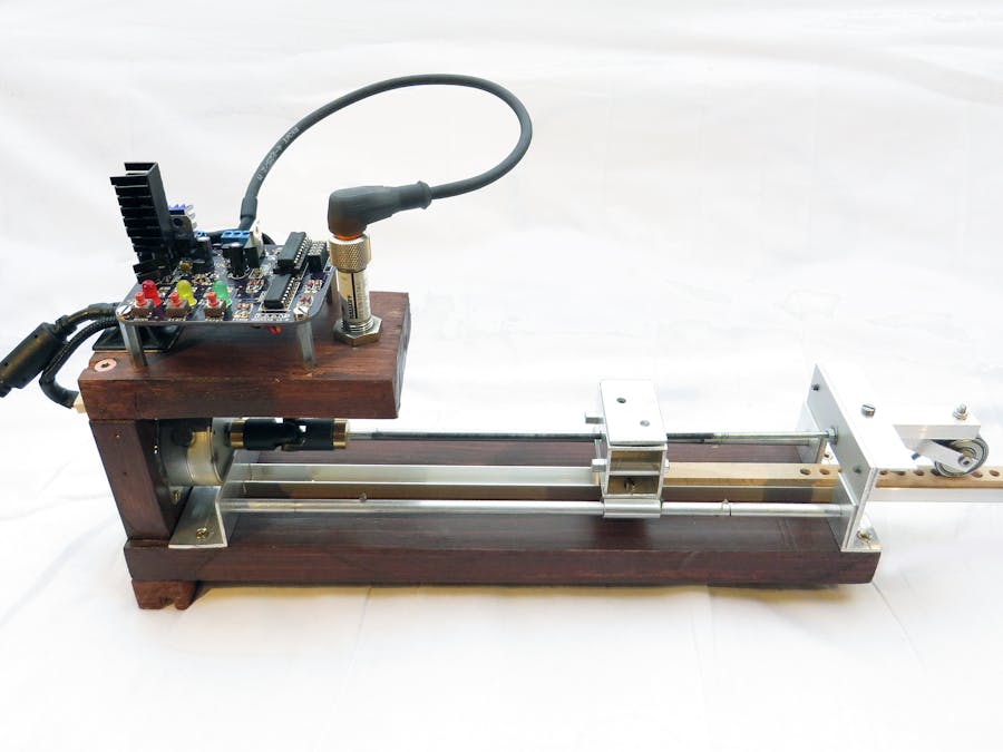
Finished Photos
I got the PCB made at OSHPark. Really great quality and price, I would use them again with no hesitation.
Currently it is mounted on my fish tank and I am doing a test while I am home to see if it works. So far it works great, no issues whatsoever. The first real test will be the Christmas holidays when we wont be home!
Cheers!


Comments
Please log in or sign up to comment.