


Hardware components | ||||||
 |
| × | 1 | |||
| × | 1 | ||||
| × | 1 | ||||
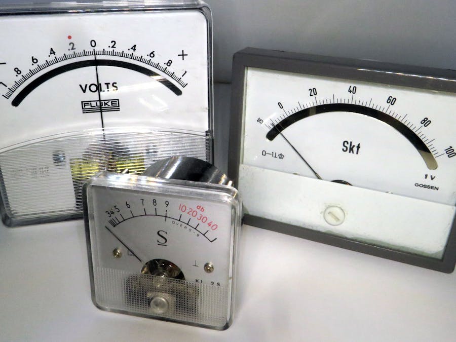
This tutorial is about how to control analog gauges with an MSP430.
Finished Effect (full range scrolling to show the motion):
In order to do this you will need:
- MSP430 (I used the MSP430G2553 but you can use almost any variant)
- Debugger (Ti Launchpad)
- C compiler (I used Code Composer Studio from Ti)
- An analog gauge
- Some resistors/transistors/wires/power supply
Planning
The gauge I chose has a range of -150mV up to 1V. On the backside there is a small PCB which has a voltage divider network creating a fullscale range of -1.5v up to 10v.
The MSP430 can output 3.3V on it's analog out ports. We need to create a method to convert 0-3.3V into 0-10v. I created this model in LTSpice:
V2 is our MSP430 analog pin. The voltage divider R1 & R5 are converting the 12v source to 10v. From there, a PWM signal on V2 will allow us to have an adjustable DC voltage at C1. This schematic gives us a range of 0v up to 10v. When the PWM is 100%, Q1 is fully on, this pulls R6 together with C1 down to 0v. When the PWM is set to 0%, Q1 is off, giving us 10v at C1.
The simulation of this circuit produces the following:
The blue signal is at the collector of Q1. The green signal is at the interface between C1 and R6. I chose a random PWM value for this trace, I guess its something near to 40-45%. You can see that there is some time required to stabilize the circuit, around 4-5mS before it reaches a steady state.
Code
I decide to write the code in C, there isn't any significant advantage to doing this for this simple program. You can write this in Energia with no issues.
The first part of the code is the function prototypes and variable declarations:
After that we go to the initial setup: stopping the watchdog timer, setting the clocks, configuring P1.0 on the MSP430.
The configureClocks function is telling the MSP430 which clocks use. I am using the internal DCO and configuring it as the source for the master clock at 16Mhz. This will change the execution time of your program. You can test this, keeping all other code the same simply configure the clock to 12, 8, or 1Mhz and check the movement of the gauge, you will see a change in the movement. Note that a 1Mhz will not produce a very high frequency on the output pin, causing some erratic movement of your gauge. The resistor R6 and capacitor C1 help to smooth this. At frequencies above 1Mhz, you don't need R6 and C1 (the video is made without these two components).
Here is where you would add the code which could manipulate the gauge in a useful way. I have two simple functions, one to make a movement from 0-100 and one for a movement from 100-0:
The functions goDown and goUp are more or less the same, only the loop is executed backwards. For simplicity I will just show the goDown function here.
What the function does is generate a PWM signal on P1.0. You have a maximum delay which is split between the two while loops. This total delay is 10000 (not a time unit, because the execution is depending on the clockspeed, this is not the same as a delay or delayms function in energia). The function then calculates the PWM with the two variables i and j using the percentagePWM variable. This variable is calculated as an increasing (or decreasing) factor (0-1). The factor is multiplied by the maximum delay for the off cycle (variable j) and multiplied by the delay and subtracted from it for the on cycle (variable i).
For example: we have an x of 249. The percentage is calculated as 0.004. This means for the on cycle we have a delay of 40 and for the off cycle we have a delay of 9960. This gives us a PWM of 0.4% (40/10000 * 100).
Another example: at the beginning of the loop x is equal to 1. The percentage is calculated as 0.996. This gives us an on cycle delay of 9960 and an off cycle delay of 40. This results in a PWM of 99.6% (9960/10000 * 100).
How to make this useful
The variable x in the function determines the %PWM you get. This means, if you want to put some meaningful data behind your gauge, you simply remove the loops which sweep through the range of PWM values and manipulate the variable x and set it to whatever you want between 0 and maximumPWM.
Have fun!


Comments
Please log in or sign up to comment.