16 relay outputs, 4 protected digital or analog inputs, WIFI, RF network, Raspberry PI engine.
Repair/assemble in minutes. Real world tough and ready.
Computing boards/modules are cheap and so are real-world interface modules. The internet of things is a "lego plug and play" world, there is absolutely no reason to try and design/build you own controller from the ground up.
These opto isolated ( very safe ) relay boards are reliable, proven, super cheap and are made by the thousands in china. They can control 240vac and DC. Forget about triacs and other clever direct to power interfaces, these relays will likely outlast your project and if it does fail, for $7 you can replace it.
The raspberry PI A has more than enough power for your control project. You can program in any language and its easy to connect to the internet. The new PI Zero coming soon is $8!
These RF transceivers are a few dollars each, they are good for 10m through walls or 50m outside. For a few dollars more you can get one with antenna & amplifiers to get some more range. We will use them on remote sensors.
( more on that later )
These step down regulator modules are cheaper on ebay than buying the parts! Stay away from trying to design and solder surface mount based projects/modules, leave that to the module suppliers and their proper wave soldering facilities.
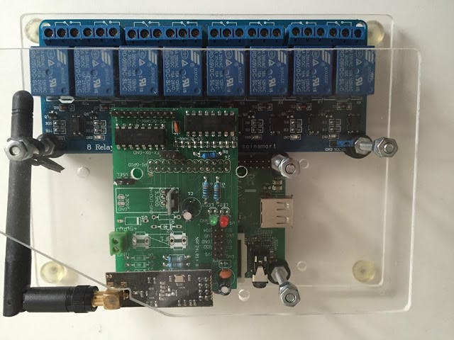
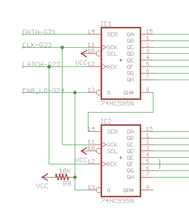
The problem with all these "lego blocks" is that your have to wire them together. And if something does fail you have de-soldering to do and the potential to re-wire incorrectly. Also lots of wires looks messy and unprofessional. The solution is to use a PCB layout program like "eagle" and send off to china to get a bunch of "Rats-Nest-Eliminator" (RNE) circuit boards made up cheaply in batches of 10-20. Here's the one I designed, the auto-router did most of the hard work, it's mostly about circuit protection & filtering, mounting, simplification and RNE, it does have a few CMOS chips ( non surface mount ) to enhance the I/O capability of the PI GPIO.
The board above does the following:
- Direct connect to the raspberry PI GPIO via underside 26 pin connector.
- Holds 2 CMOS shift registers to give us 16 latched outputs
- Direct connect to the relay board via 8 of the CMOS outputs and underside 10 pin connector
- Have a ribbon cable interface for another expansion relay board
- Hold a 5 to 3.3v regulator module to power the RF
- Interface via PI SPI to the RF transceiver module
- Provide two leds for status and warnings
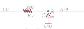
- Provide simple input overvoltage/spike protection for 4 inputs to the PI
- Will take 24AC/DC via DC-DC Adjustable LM2596 Step Down Module Buck Converter module ( ebay for $3 ) if not powered by USB.
- Connects all the main modules together to create a space efficient package.
So here is the finished controller. Not one wire needed. All mounting via 4 bolts that act as case spacers. The case is just two sheets of perspex with a few drilled holes. Can be pulled apart and reassemble in a minute or two. All boards held in place by their connection to the RNE board and via rubber grommets to the base so there is less chance of module damage during temperature changes and when screwing wire into the relays.
I have worked professionally in electrical computer process control in the 80's and 90's and have designed this unit with the lessons learned. Here are the design principles:
- Good visibility to health/condition, easy to dismantle to clean & fault find.
- Excellent air circulation. - electronics mounted outside in cabinets can get very hot
- Ugly and simple is fine, no one sees the controller when it's working well.
- Physical protection from tool slips and drops, sensitive parts should never touch case walls
- Replacement parts should be cheap and common and held on hand, no wasted time trying to fix modules
- All parts/modules plug-n-play, should be able to disassemble and reassemble without a manual!
- Use proven modules, avoid custom complex circuits that can hide future problems.
- Eliminate wires & 1-3 pin interfaces, 8-16 pin connectors are much more robust and reliable. So disposable we don't even bother with CMOS chip holders
- Simple surge/overvoltage protection. If the parts are inexpensive there is no point going over the top with protection circuits, the unit is just as likely to be destroyed by crushing/dropping.
- No setting-up buttons, text menus etc etc. No one has time to learn all that. You need a green flashing led saying all is good and a red led flashing a count from 1-10 repeatedly indicating an error. Connect via laptop and WIFI to monitor logs and make programming changes
- Stay connected periodically to the internet so we can interface to cloud monitoring and time sync services.
- Always run watchdog processes over your main control programs
Contact me if you would like to purchase the "Rats-Nest-Eliminator" (RNE) bare board in bulk for project or education or re-seller purposes. 2x Individual bare boards will be $20us ( to cover international postage ) Packs of 20 boards will be $50us.
The first use of this controller will be for irrigation control. It will spend its ( hopefully long ) life locked in an IP67 waterproof enclosure. Full set of spare parts will be kept nearby to absolutely minimise downtime.
Not keen to open source the RNE board, it's a concept that I would like to develop further for other commercial projects. The smarts here are in the layout & 3 level mounting arrangements, circuit design is kept as simple as possible for reliability.


Comments
Please log in or sign up to comment.