


Hardware components | ||||||
_ztBMuBhMHo.jpg?auto=compress%2Cformat&w=48&h=48&fit=fill&bg=ffffff) |
| × | 1 | |||
 |
| × | 1 | |||
 |
| × | 1 | |||
 |
| × | 1 | |||
 |
| × | 1 | |||
🔋 How to Make an Autocaut Charging Mini DC IPS at Home | DIY Backup Power Supply | Step-by-Step Guide 🔋
In today’s world, having a reliable power backup solution is more important than ever, especially in areas where power outages are frequent. A cost-effective and efficient way to address this problem is by building your own Autocaut Charging Mini DC IPS (Instant Power Supply) at home. This DIY project is perfect for keeping low-power devices like LED lights, fans, or internet routers running during power cuts, ensuring uninterrupted comfort and connectivity.
In this blog, we’ll walk you through everything you need to know to make your own Mini DC IPS, using Autocaut charging technology to provide sustainable and automatic backup power. Let’s dive in!
What is an Autocaut Charging Mini DC IPS?A Mini DC IPS is a small-scale, DC-based backup power supply designed to provide instant electricity to essential devices when the main power goes out. The Autocaut charging system ensures that the backup battery is automatically charged from the grid or solar power, and instantly kicks in to supply power when an outage occurs.
Unlike traditional inverters that convert DC to AC power, the Mini DC IPS directly powers DC devices, making it more energy-efficient and reducing conversion losses.
Why Build Your Own Mini DC IPS?- Cost-Effective: Commercial backup systems can be expensive. By making your own Mini DC IPS, you can save a lot of money while still having a reliable power solution.
- Customization: Tailor the system to your specific needs, such as device compatibility or adding renewable energy options like solar charging.
- Sustainability: The system can be paired with solar panels, making it an eco-friendly option for power backup.
- Learning Opportunity: This project is a great way to learn about electronics, power systems, and renewable energy, making it ideal for students, DIY enthusiasts, and anyone looking to enhance their technical skills.
Before you get started, gather the following materials:
- Rechargeable Battery (preferably 12V, but can vary based on your need)
- DC-to-DC Converter to regulate output power
- Autocaut Charging Circuit for automatic battery charging
- Inverter (optional, if you need to power AC devices)
- Wires, Connectors, and Basic Tools (like a soldering iron, screwdriver, and multimeter)
- Solar Panel (Optional) for solar-powered charging
The core of your Mini DC IPS lies in the Autocaut charging circuit. This circuit is responsible for managing the charging of the battery and ensuring the battery is charged safely and efficiently. The system will automatically switch to battery power during an outage and revert to mains power when it’s restored.
Step 2: Connect the BatteryThe rechargeable battery stores energy, which will be used during power outages. Connect the battery to the Autocaut charging circuit, ensuring the positive and negative terminals are correctly aligned.
Step 3: Install the DC-to-DC ConverterThe DC-to-DC converter is critical in regulating the output voltage and current from the battery to your devices. Ensure that the converter matches the required voltage of the devices you plan to power.
Step 4: Wiring and Testing the Autocaut Charging CircuitUse appropriate wiring to connect the Autocaut charging circuit to the battery and the DC-to-DC converter. After wiring, test the system by connecting a low-power DC device, such as an LED light, and observe how it works when the main power supply is turned off.
JLCPCB PCB Fab & Assembly from $2! Sign up to Get $60 Coupons: https://jlcpcb.com/?from=EST
Up to 50% off! Get FREE 6-layer PCBs during JLCPCB Engineers Day : https://jlcpcb.com/engineers-day?from=ACT
Step 5: Adding a Solar Panel (Optional)Those looking to integrate renewable energy into their backup system can add a solar panel to charge their battery during the day. Connect the solar panel to the Autocaut charging circuit, which will manage the charging process from solar energy as well.
Step 6: Housing the IPS SystemOnce your wiring and connections are tested and working, place the components in a secure and ventilated housing to protect them from dust, moisture, and accidental short circuits.
Benefits of an Autocaut Charging Mini DC IPS- Automatic Backup Power: The Autocaut charging system ensures the battery is automatically charged and ready to supply power without manual intervention.
- Energy Efficiency: By delivering power directly to DC devices, this system minimizes energy loss.
- Scalable and Customizable: You can adjust the system’s capacity to fit your power needs, whether for a few lights or a more substantial load like a router or fan.
- Environmentally Friendly: When paired with solar panels, the Mini DC IPS can provide renewable energy backup, reducing your carbon footprint.
This compact and efficient backup power system is ideal for:
- Home use: Powering LED lights, fans, or modems during outages.
- Remote locations: Providing electricity in off-grid or rural areas.
- Outdoor activities: Portable power supply for camping or outdoor events.
- Emergency situations: Ensuring basic devices remain powered during natural disasters or emergencies.
To ensure the longevity and efficiency of your Mini DC IPS, follow these simple maintenance tips:
- Regularly check the battery for corrosion and ensure it’s holding a proper charge.
- Test the system periodically to make sure it switches to backup mode seamlessly.
- Keep the housing clean and dry to prevent damage to the internal components.
- If using solar panels, clean the panels regularly to ensure they capture maximum sunlight for charging.
If you’ve built your own Autocaut Charging Mini DC IPS, let us know in the comments! Share your tips, challenges, or any customizations you made to the project.
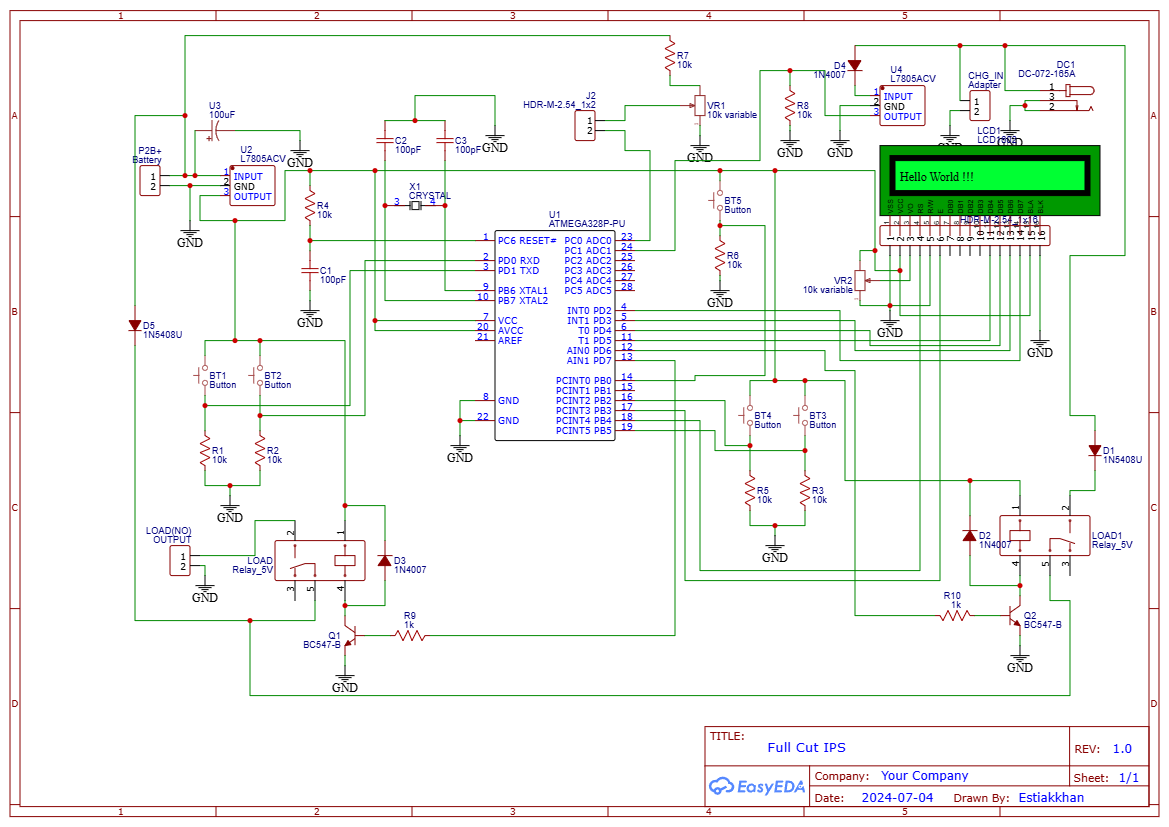
Looking for more DIY power projects? Check out our other tutorials on sustainable energy solutions and backup power systems!If you're looking for an affordable and efficient way to build your own Autocaut Charging Mini DC IPS, incorporating microcontroller technology like the Atmega328P IC can provide more advanced automation and control. This enhanced version of the DIY Mini DC IPS includes an automatic battery charge controller, automatic load management when electricity is available, and a manual override push button for controlling the load.
In this blog, we'll show you how to integrate components such as the Atmega328P microcontroller, DC relay, and essential electronic components to create a smart backup power supply that can handle automatic switching, battery management, and manual load control.
Materials You Need for the Autocaut Charging Mini DC IPSBefore getting started, make sure you have the following components ready:
- Atmega328P IC (Microcontroller)
- Crystal 16Mhz (for stable clocking of the Atmega328P)
- 103VR Capacitor (for voltage regulation)
- 10K Resistor (pull-up for reset pin)
- DC Relay 5V 2P (to switch the load automatically)
- BC547 Transistor (for relay control)
- 1K Resistor (base resistor for the transistor)
- 22pf Capacitors (for crystal oscillator stabilization)
- 104pf Capacitors (for filtering)
- L7805 Voltage Regulator (to regulate the input voltage to 5V for the microcontroller)
- Rechargeable Battery (12V recommended)
- Solar Panel (Optional for renewable charging)
- Push Button (for manual load control)
- Autocaut Charging Circuit (automatic battery charging)
- Wires, Connectors, and Basic Tools (soldering iron, multimeter, etc.)
- Atmega328P IC: This is the brain of the system, controlling the relay, monitoring the battery charging status, and deciding when to turn the load on or off based on power availability.
- Crystal 16Mhz: The external clock ensures stable operation of the Atmega328P.
- Automatic Battery Charging: The system will continuously monitor the battery and charge it automatically when necessary, using a DC charging circuit integrated with the Atmega328P.
- Load On/Off Control: The relay will control the load (lights, fans, etc.), automatically turning it on during outages and switching it off when the grid power is restored.
- Manual Override: The push button allows manual control of the load, letting you turn it on or off as needed.
- Place the Atmega328P microcontroller on a breadboard or PCB.
- Connect the 16Mhz crystal between the XTAL1 and XTAL2 pins of the Atmega328P.
- Attach 22pf capacitors from each crystal leg to ground.
- Connect a 10K resistor from the reset pin (pin 1) to Vcc as a pull-up resistor.
- Use the L7805 voltage regulator to step down your battery’s 12V to 5V to power the Atmega328P and other low-voltage components.
- Connect 104pf capacitors to the input and output pins of the L7805 for stability.
- Power the Atmega328P through its Vcc and GND pins.
- Connect the Autocaut charging circuit to the 12V battery and integrate it with the Atmega328P.
- The Atmega328P will monitor the battery voltage via an analog input pin and control the charging based on the battery’s state of charge.
- You can program the microcontroller to stop charging when the battery is full and start again when it drops below a certain threshold.
- Use a 5V DC relay to control the load (such as lights or fans).
- The BC547 transistor will act as a switch for the relay, controlled by the Atmega328P.
- Connect the base of the BC547 to an output pin of the Atmega328P via a 1K resistor. The emitter connects to GND, and the collector connects to the relay’s coil.
- When the microcontroller sends a signal to the transistor’s base, it activates the relay, which will power your load.
- Program the Atmega328P to sense the presence of grid power. You can use an optocoupler circuit or voltage detection method to detect whether mains power is present.
- When the power is ON, the microcontroller will deactivate the relay, turning off the load.
- When power goes OFF, the Atmega328P will switch the relay to ON, providing backup power to the load.
- Attach a push button to an input pin of the Atmega328P, with a 10K pull-down resistor to ensure it stays in a LOW state when not pressed.
- Program the button to toggle the state of the load (on or off) manually. This will allow you to override the automatic system if needed.
16x2 LCD without I2C: Connect the LCD display to the Atmega328P in 4-bit mode:
- RS to digital pin 12
- E to digital pin 11
- D4-D7 to digital pins 5-2
- VSS to GND, VDD to 5V
- RW to GND
- Connect the 10K potentiometer to adjust the contrast: one leg to 5V, one leg to GND, and the wiper (middle leg) to the VO pin of the LCD.
- 16x2 LCD without I2C: Connect the LCD display to the Atmega328P in 4-bit mode:RS to digital pin 12E to digital pin 11D4-D7 to digital pins 5-2VSS to GND, VDD to 5VRW to GNDConnect the 10K potentiometer to adjust the contrast: one leg to 5V, one leg to GND, and the wiper (middle leg) to the VO pin of the LCD.
16x2 LCD with I2C Module: For a simpler setup, connect the SDA and SCL pins of the I2C module to A4 and A5 of the Atmega328P, respectively. Power the LCD with 5V and GND from the microcontroller.
- 16x2 LCD with I2C Module: For a simpler setup, connect the SDA and SCL pins of the I2C module to A4 and A5 of the Atmega328P, respectively. Power the LCD with 5V and GND from the microcontroller.
We’ll need to update the code for the Atmega328P to display information on the 16x2 LCD.
If you’re using the LCD with I2C, include the LiquidCrystal_I2C library:
#include <Wire.h>
#include <LiquidCrystal_I2C.h>
LiquidCrystal_I2C lcd(0x27, 16, 2); // Set the I2C address to 0x27 for a 16 chars and 2 line display
For a direct LCD connection without I2C, use the LiquidCrystal library:
#include <LiquidCrystal.h>
LiquidCrystal lcd(12, 11, 5, 4, 3, 2); // RS, E, D4, D5, D6, D7
Display Information on the LCDNow, we’ll modify the code to display the battery voltage, charging status, and whether the load is ON or OFF.
Display Information on the LCDNow, we’ll modify the code to display the battery voltage, charging status, and whether the load is ON or OFF.
int relayPin = 7; // Relay control pin
int buttonPin = 2; // Push button pin
int chargePin = A0; // Pin to monitor battery voltage
int loadState = LOW; // Initial state of the load
bool manualControl = false; // Flag for manual override
float batteryVoltage = 0.0;
void setup() {
pinMode(relayPin, OUTPUT);
pinMode(buttonPin, INPUT);
lcd.begin(16, 2); // Initialize the LCD
lcd.setBacklight(1); // Turn on the backlight
Serial.begin(9600);
}
void loop() {
int buttonState = digitalRead(buttonPin);
int sensorValue = analogRead(chargePin); // Read battery voltage
batteryVoltage = (sensorValue * (5.0 / 1023.0)) * 4; // Adjust for 12V battery
// Automatic battery charging logic
if (batteryVoltage < 11.5) { // Low voltage
digitalWrite(relayPin, HIGH); // Turn relay ON (load powered)
lcd.setCursor(0, 0);
lcd.print("Charging: ON");
} else if (batteryVoltage > 13.5) { // Battery full
digitalWrite(relayPin, LOW); // Turn relay OFF (stop charging)
lcd.setCursor(0, 0);
lcd.print("Charging: OFF");
}
// Display battery voltage
lcd.setCursor(0, 1);
lcd.print("Battery: ");
lcd.print(batteryVoltage);
lcd.print("V");
// Manual control using push button
if (buttonState == HIGH && !manualControl) {
manualControl = true;
loadState = !loadState; // Toggle load state
digitalWrite(relayPin, loadState);
} else if (buttonState == LOW) {
manualControl = false;
}
// Display load state
lcd.setCursor(10, 0);
if (loadState == HIGH) {
lcd.print("Load: ON ");
} else {
lcd.print("Load: OFF");
}
delay(100); // Small delay for debounce
}
Video Reference:JLCPCB PCB Fab & Assembly from $2! Sign up to Get $60 Coupons: https://jlcpcb.com/?from=EST
Up to 50% off! Get FREE 6-layer PCBs during JLCPCB Engineers Day : https://jlcpcb.com/engineers-day?from=ACT
Wiring the Relay and Transistor for Load Control- Follow the steps from the previous guide to wire the BC547 transistor and DC relay. The Atmega328P will control the relay based on the battery voltage, and the LCD will show the status of the relay (ON/OFF).
- Connect the push button to an input pin (pin 2), allowing manual control over the load.
- Power the Atmega328P using the L7805 voltage regulator to step down the 12V battery to 5V.
- Upload the code and check that the LCD display is showing the correct information: battery voltage, charging status, and load state.
- Test the system by disconnecting and reconnecting the main power to see if the system switches to battery power and turns the load on automatically. Verify that the manual push button correctly toggles the load.
- Once the system is fully tested, house all components in a secure, ventilated enclosure.
- Ensure that the LCD display is visible so you can monitor the system's status at any time.
Adding a 16x2 LCD display to your Autocaut Charging Mini DC IPS makes the system more functional and user-friendly by allowing you to monitor real-time data like battery voltage and load status. The integration of the Atmega328P microcontroller provides automatic load switching and battery management, while the manual push button gives you the ability to control the load manually when necessary.
This project not only enhances your DIY power backup system but also helps you gain a deeper understanding of embedded systems, electronics, and renewable energy solutions.


Comments
Please log in or sign up to comment.