


Hardware components | ||||||
 |
| × | 1 | |||
 |
| × | 1 | |||
 |
| × | 1 | |||
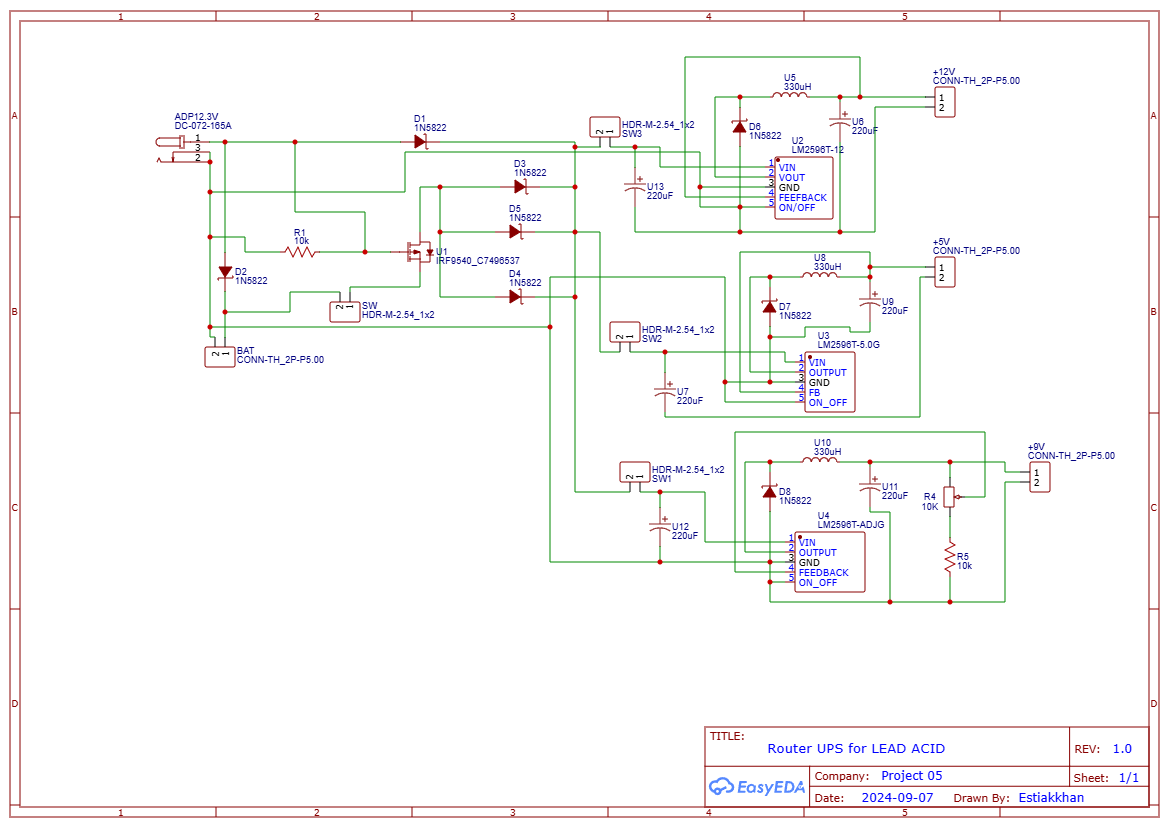
Are you tired of losing your internet connection during power outages? A reliable WiFi Router UPS (Uninterruptible Power Supply) can save the day! In this guide, we'll walk you through building a WiFi Router UPS that takes a 16V or 24V DC input and provides stable outputs at 12V, 9V, and 5V. With the help of the attached schematic, you can keep your essential networking equipment powered even when the grid fails.
OverviewThis project is designed for enthusiasts looking to build a simple yet effective UPS for their WiFi router or other low-power devices. It ensures seamless internet connectivity by switching to backup power without interruptions.
Discover Easy, Affordable, and Reliable PCB manufacturing with JLCPCB!Register to get $60 New customer coupons:https://jlcpcb.com/?from=EST
Special Deal: Get a $30 coupon for JLCPCB premium 6-layer PCBs:
https://jlcpcb.com/6-layer-pcb?from=getcoupon
Key Features:- Input Voltage: 16V or 24V DC
- Output Voltages: 12V, 9V, and 5V DC
- Battery Backup: Supports lead-acid batteries
- Overload Protection: Built-in safeguards using robust diodes and regulators
- Compact Design: Easily integrates into your home or office setup
The circuit uses three LM2596 step-down voltage regulators to convert the input voltage into three output voltages: 12V, 9V, and 5V. Here's a breakdown of the components and their roles:
Input Section:
- The input voltage (16V or 24V) is fed through protection diodes (1N5822) to ensure reverse polarity protection.
- A lead-acid battery is connected for backup power, automatically engaging when the main power supply fails.
- Input Section:The input voltage (16V or 24V) is fed through protection diodes (1N5822) to ensure reverse polarity protection.A lead-acid battery is connected for backup power, automatically engaging when the main power supply fails.
Voltage Regulators:
- Three LM2596 modules regulate the output to 12V, 9V, and 5V.
- Inductors (330µH) and capacitors (220µF) stabilize the output, ensuring clean and noise-free power.
- Voltage Regulators:Three LM2596 modules regulate the output to 12V, 9V, and 5V.Inductors (330µH) and capacitors (220µF) stabilize the output, ensuring clean and noise-free power.
Switching Mechanism:
Discover Easy, Affordable, and Reliable PCB manufacturing with JLCPCB!Register to get $60 New customer coupons:https://jlcpcb.com/?from=EST
Special Deal: Get a $30 coupon for JLCPCB premium 6-layer PCBs:
https://jlcpcb.com/6-layer-pcb?from=getcoupon
- The MOSFET (IRF9540) facilitates smooth switching between input power and battery backup.
- The circuit prioritizes the main supply but instantly switches to battery power during an outage.
- Switching Mechanism:The MOSFET (IRF9540) facilitates smooth switching between input power and battery backup.The circuit prioritizes the main supply but instantly switches to battery power during an outage.
Output Terminals:
- The three outputs are routed through connectors for easy access to power routers, modems, or any compatible device.
- Output Terminals:The three outputs are routed through connectors for easy access to power routers, modems, or any compatible device.
The attached schematic provides a detailed layout for building the circuit. Here's a quick explanation of the key sections:
- Protection Diodes (D1, D2, D3): Ensure no reverse current flows into the circuit.
- Voltage Regulators (U2, U3, U4): Deliver stable 12V, 9V, and 5V outputs.
- Capacitors (U7, U8, U10): Filter and stabilize the voltage for steady operation.
- Switch (SW1): Allows manual control of the UPS function.
- LM2596 Voltage Regulator Modules (x3)
- IRF9540 MOSFET
- 1N5822 Diodes (x8)
- Capacitors: 220µF (x4)
- Inductors: 330µH (x3)
- Lead-Acid Battery
- Connectors and Switches
- Follow the schematic to connect all components. Use a breadboard for initial testing, then move to a PCB for final assembly.
- Ensure proper soldering of components to avoid connection issues.
- Connect a 16V or 24V power source to the input terminals.
- Verify the output voltages with a multimeter.
- Test the battery backup functionality by disconnecting the main power supply.
- Mount the assembled circuit in a compact, heat-dissipating enclosure.
- Connect your WiFi router and other devices to the output terminals.
Discover Easy, Affordable, and Reliable PCB manufacturing with JLCPCB!Register to get $60 New customer coupons:https://jlcpcb.com/?from=EST
Special Deal: Get a $30 coupon for JLCPCB premium 6-layer PCBs:
https://jlcpcb.com/6-layer-pcb?from=getcoupon
Applications- Home WiFi Routers
- Modems and Network Switches
- IoT Devices
- Raspberry Pi or Arduino Projects
This WiFi Router UPS is a must-have for anyone looking to maintain uninterrupted internet access during power cuts. By following this guide and the provided schematic, you can create a reliable and efficient power backup system tailored to your needs.


Comments
Please log in or sign up to comment.