

Hardware components | ||||||
 |
| × | 1 | |||
| × | 1 | ||||
 |
| × | 1 | |||
 |
| × | 1 | |||
 |
| × | 1 | |||
 |
| × | 1 | |||
The goal of this inverter project is to create a device capable of generating stable AC output from a DC source. This is achieved through high-frequency switching, power MOSFETs, and a transformer. The inverter is ideal for backup power applications or powering small loads like LED lights, fans, or low-power electronics.
Build a Pure Sine Wave 200-300W Power InverterThe goal of this inverter project is to create a device capable of generating stable AC output from a DC source. This is achieved through high-frequency switching, power MOSFETs, and a transformer. The inverter is ideal for backup power applications or powering small loads like LED lights, fans, or low-power electronics.
SuppliesHow the Inverter WorksInverter circuits convert DC power from a battery into AC power. In this design:
- EGS002 Module generates SPWM (Sine Pulse Width Modulation) signals to control the MOSFETs.
- The MOSFETs rapidly switch the DC current on and off, creating a high-frequency AC waveform.
- A UPS transformer then steps up the low-voltage AC to a standard AC voltage (110V or 220V).
- The resulting AC output can power small appliances, providing a portable AC source.
SuppliesHow the Inverter WorksInverter circuits convert DC power from a battery into AC power. In this design:EGS002 Module generates SPWM (Sine Pulse Width Modulation) signals to control the MOSFETs.The MOSFETs rapidly switch the DC current on and off, creating a high-frequency AC waveform.A UPS transformer then steps up the low-voltage AC to a standard AC voltage (110V or 220V).The resulting AC output can power small appliances, providing a portable AC source.
Step 1: Components Required- IRFZ44N / IRF3205 MOSFETs: These handle high currents and act as the main switching components.
- EGS002 Module: This SPWM module generates the sine wave control signal, ensuring smooth and stable AC output.
- UPS Transformer: Converts low-voltage AC from the MOSFET switching to a higher AC voltage (110V or 220V).
- Battery (12V): Provides the DC input power for the inverter.
- Resistors: 10Ω and 4.7kΩ resistors to control current and voltage through the circuit.
- Capacitors:
- 4700µF, 100µF, and 10µF electrolytic capacitors to filter and smooth the DC and AC voltages.
- 104 ceramic capacitor for additional smoothing.
- Diodes:
- FR107 fast recovery diode for efficient switching.
- 1N4148 Zener Diode for voltage regulation.
- Feedback Capacitor (225J): Adds stability to the transformer’s feedback loop.
- Fuse 15A: Protects against overcurrent.
- Switch: Controls power to the circuit.
- AC Socket: For output AC connections.
- JLCPCB Custom PCB Board: Organizes components for a stable, neat layout.
Step 1: Components RequiredGet JLCPCB 6-layer PCBs for just $5! Register to get $80 Coupons: https://jlcpcb.com/?from=EST1. Core ComponentsIRFZ44N / IRF3205 MOSFETs: These handle high currents and act as the main switching components.EGS002 Module: This SPWM module generates the sine wave control signal, ensuring smooth and stable AC output.UPS Transformer: Converts low-voltage AC from the MOSFET switching to a higher AC voltage (110V or 220V).Battery (12V): Provides the DC input power for the inverter.2. Supporting ComponentsResistors: 10Ω and 4.7kΩ resistors to control current and voltage through the circuit.Capacitors:4700µF, 100µF, and 10µF electrolytic capacitors to filter and smooth the DC and AC voltages.104 ceramic capacitor for additional smoothing.Diodes:FR107 fast recovery diode for efficient switching.1N4148 Zener Diode for voltage regulation.Feedback Capacitor (225J): Adds stability to the transformer’s feedback loop.Fuse 15A: Protects against overcurrent.Switch: Controls power to the circuit.AC Socket: For output AC connections.JLCPCB Custom PCB Board: Organizes components for a stable, neat layout.
Step 2: Choosing the Right MOSFETsSelecting the best MOSFETs is crucial for efficient and reliable inverter performance.
- IRFZ44N: Rated for 49A and 55V, a cost-effective option for moderate power.
- IRF3205: Rated for 110A and 55V with lower R_DS(on), which leads to less heating and better efficiency, ideal for this 200-300W inverter.
- 95N03 MOSFET: Another option with a very low R_DS(on), suitable for high-efficiency needs but not as widely available as IRF3205.
Recommendation: IRF3205 is the best choice due to its high current rating, low on-resistance (for minimal heating), and durability, especially for extended use at high loads.
Step 2: Choosing the Right MOSFETsSelecting the best MOSFETs is crucial for efficient and reliable inverter performance.IRFZ44N: Rated for 49A and 55V, a cost-effective option for moderate power.IRF3205: Rated for 110A and 55V with lower R_DS(on), which leads to less heating and better efficiency, ideal for this 200-300W inverter.95N03 MOSFET: Another option with a very low R_DS(on), suitable for high-efficiency needs but not as widely available as IRF3205.Recommendation: IRF3205 is the best choice due to its high current rating, low on-resistance (for minimal heating), and durability, especially for extended use at high loads.
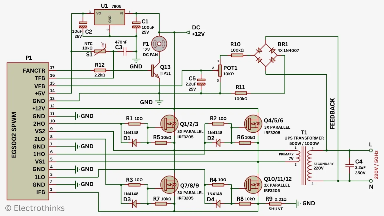
Step 3: Circuit Block Diagram- The 12V battery provides DC power to the circuit.
- A 15A fuse connects in series with the positive terminal, offering overcurrent protection.
- The EGS002 SPWM module controls the MOSFET gates, creating a 50Hz or 60Hz sine wave output.
- Connect the battery directly to the module’s power input, ensuring stable DC supply.
- Connect IRF3205 MOSFETs in parallel, as they will handle the inverter’s main power load.
- The EGS002 drives the gates of these MOSFETs, rapidly switching them on and off, producing an AC waveform.
- Gate Resistors (10Ω): Add a 10Ω resistor to each MOSFET gate pin to limit inrush current and prevent gate damage.
- The UPS transformer is connected to the MOSFETs’ output to convert the low-voltage AC into high-voltage AC.
- The 225J feedback capacitor stabilizes the transformer’s output, ensuring stable AC voltage output.
- Use 4700µF, 100µF, and 10µF capacitors for smoothing the DC and AC waveforms.
- Place the capacitors across the power input and output to reduce noise and smooth out voltage spikes.
- The transformed AC voltage is routed to the AC socket for connecting appliances.
- Add a switch to control the inverter’s power output, allowing you to turn off the AC when not in use.
Step 3: Circuit Block DiagramDetailed Circuit Design1. Battery and Fuse SetupThe 12V battery provides DC power to the circuit.A 15A fuse connects in series with the positive terminal, offering overcurrent protection.2. EGS002 ModuleThe EGS002 SPWM module controls the MOSFET gates, creating a 50Hz or 60Hz sine wave output.Connect the battery directly to the module’s power input, ensuring stable DC supply.3. MOSFET Switching StageConnect IRF3205 MOSFETs in parallel, as they will handle the inverter’s main power load.The EGS002 drives the gates of these MOSFETs, rapidly switching them on and off, producing an AC waveform.Gate Resistors (10Ω): Add a 10Ω resistor to each MOSFET gate pin to limit inrush current and prevent gate damage.4. TransformerThe UPS transformer is connected to the MOSFETs’ output to convert the low-voltage AC into high-voltage AC.The 225J feedback capacitor stabilizes the transformer’s output, ensuring stable AC voltage output.5. Filtering CapacitorsUse 4700µF, 100µF, and 10µF capacitors for smoothing the DC and AC waveforms.Place the capacitors across the power input and output to reduce noise and smooth out voltage spikes.6. AC Output and SocketThe transformed AC voltage is routed to the AC socket for connecting appliances.Add a switch to control the inverter’s power output, allowing you to turn off the AC when not in use.
Step 4: Heat Dissipation and MOSFET ProtectionProper heat dissipation is crucial for MOSFETs in power circuits due to the high currents involved. Without adequate cooling, MOSFETs can overheat and fail.
- Heat Sink Selection:
- Use large aluminum heatsinks for each MOSFET, capable of dissipating 20-50W.
- The IRF3205 MOSFETs, in particular, require large heatsinks if running continuously under load.
- Thermal Paste:
- Apply thermal paste between the MOSFET and heatsink to enhance heat transfer.
- This reduces heat build-up, prolonging MOSFET life.
- Active Cooling:
- Place a 12V fan near the heatsinks to maintain airflow, especially useful if the inverter will be used continuously.
Step 4: Heat Dissipation and MOSFET ProtectionProper heat dissipation is crucial for MOSFETs in power circuits due to the high currents involved. Without adequate cooling, MOSFETs can overheat and fail.Heat Sink Selection:Use large aluminum heatsinks for each MOSFET, capable of dissipating 20-50W.The IRF3205 MOSFETs, in particular, require large heatsinks if running continuously under load.Thermal Paste:Apply thermal paste between the MOSFET and heatsink to enhance heat transfer.This reduces heat build-up, prolonging MOSFET life.Active Cooling:Place a 12V fan near the heatsinks to maintain airflow, especially useful if the inverter will be used continuously.
Step 5: Protecting MOSFETs From Overload and Damage- Overcurrent Protection:
- The 15A fuse prevents high current from damaging the MOSFETs, protecting the circuit from overloads.
- Snubber Circuit:
- Add a snubber circuit (a combination of a resistor and capacitor) across each MOSFET to absorb voltage spikes and protect against transients.
- Use a 100Ω resistor and a 0.1µF capacitor in series to provide adequate snubbing.
- Gate Protection:
- Place a 15V Zener diode across the gate and source pins of each MOSFET. This prevents excessive gate voltage, which could permanently damage the MOSFET.
- Capacitive Load Isolation:
- Avoid powering inductive or capacitive loads directly from the inverter, as they can cause high inrush currents. Start the inverter with a light load to reduce strain on the MOSFETs.
Step 5: Protecting MOSFETs From Overload and DamageOvercurrent Protection:The 15A fuse prevents high current from damaging the MOSFETs, protecting the circuit from overloads.Snubber Circuit:Add a snubber circuit (a combination of a resistor and capacitor) across each MOSFET to absorb voltage spikes and protect against transients.Use a 100Ω resistor and a 0.1µF capacitor in series to provide adequate snubbing.Gate Protection:Place a 15V Zener diode across the gate and source pins of each MOSFET. This prevents excessive gate voltage, which could permanently damage the MOSFET.Capacitive Load Isolation:Avoid powering inductive or capacitive loads directly from the inverter, as they can cause high inrush currents. Start the inverter with a light load to reduce strain on the MOSFETs.
Step 6: AC Load Connection- Install the AC Socket:
- Connect the AC output from the transformer’s secondary winding to the AC socket, allowing easy connection of appliances.
- Grounding:
- Ensure the AC output socket is grounded to protect against potential shocks and improve device safety.
- Load Testing:
- Begin with a small load, such as a light bulb, to verify the AC output.
- Gradually increase the load to reach 200-300W, monitoring the voltage stability.
Step 6: AC Load ConnectionInstall the AC Socket:Connect the AC output from the transformer’s secondary winding to the AC socket, allowing easy connection of appliances.Grounding:Ensure the AC output socket is grounded to protect against potential shocks and improve device safety.Load Testing:Begin with a small load, such as a light bulb, to verify the AC output.Gradually increase the load to reach 200-300W, monitoring the voltage stability.
Step 7: Final Testing and Optimization- Frequency and Voltage Check:
- Use an oscilloscope to check the output frequency and ensure it’s set to 50Hz or 60Hz.
- Verify the output voltage matches the expected 110V or 220V, depending on your region.
- Thermal Monitoring:
- Run the inverter under load and monitor the temperature of MOSFETs. If they become excessively hot, increase heatsink size or add more fans.
- Long-Term Operation:
- For extended use, check connections periodically and ensure all components, especially MOSFETs and capacitors, are functioning correctly.
Step 7: Final Testing and OptimizationFrequency and Voltage Check:Use an oscilloscope to check the output frequency and ensure it’s set to 50Hz or 60Hz.Verify the output voltage matches the expected 110V or 220V, depending on your region.Thermal Monitoring:Run the inverter under load and monitor the temperature of MOSFETs. If they become excessively hot, increase heatsink size or add more fans.Long-Term Operation:For extended use, check connections periodically and ensure all components, especially MOSFETs and capacitors, are functioning correctly.
Step 8: Why Choose JLCPCB for Your PCB Needs?Get JLCPCB 6-layer PCBs for just $5! Register to get $80 Coupons: https://jlcpcb.com/?from=EST
When building your inverter or any other DIY electronics project, having a high-quality, reliable PCB is essential for performance and durability. JLCPCB is a trusted choice for PCB manufacturing, offering professional-grade PCBs at affordable prices, starting at just $2 for 1-4 layer boards!
Why Choose JLCPCB for Your PCB Needs?- High-Quality Manufacturing: JLCPCB uses advanced manufacturing techniques to produce durable, precise boards, ensuring your circuit performs optimally.
- Quick Turnaround: With JLCPCB’s fast production and shipping, you can receive your custom PCBs in just a few days.
- Custom Options: Choose from a range of thicknesses, colors, and finishes to match your project’s specific requirements.
- Affordable Pricing: With prices as low as $2 for standard PCBs, JLCPCB makes professional PCB fabrication accessible to hobbyists and professionals alike.
- Reliable Customer Support: JLCPCB’s dedicated support team ensures a smooth experience from design upload to delivery.
- Design Your Circuit: Complete your design in any PCB design software, like KiCad or Altium.
- Upload to JLCPCB: Visit JLCPCB.com and upload your Gerber files.
- Customize and Order: Select your specifications, choose the shipping speed, and place your order.
JLCPCB is the best choice to bring your DIY inverter project to life with a quality PCB, ensuring cleaner layouts, improved reliability, and a professional finish to your build. Visit JLCPCB and get started on your custom PCB order today!
Step 8: Why Choose JLCPCB for Your PCB Needs?Get JLCPCB 6-layer PCBs for just $5! Register to get $80 Coupons: https://jlcpcb.com/?from=ESTWhen building your inverter or any other DIY electronics project, having a high-quality, reliable PCB is essential for performance and durability. JLCPCB is a trusted choice for PCB manufacturing, offering professional-grade PCBs at affordable prices, starting at just $2 for 1-4 layer boards!Why Choose JLCPCB for Your PCB Needs?High-Quality Manufacturing: JLCPCB uses advanced manufacturing techniques to produce durable, precise boards, ensuring your circuit performs optimally.Quick Turnaround: With JLCPCB’s fast production and shipping, you can receive your custom PCBs in just a few days.Custom Options: Choose from a range of thicknesses, colors, and finishes to match your project’s specific requirements.Affordable Pricing: With prices as low as $2 for standard PCBs, JLCPCB makes professional PCB fabrication accessible to hobbyists and professionals alike.Reliable Customer Support: JLCPCB’s dedicated support team ensures a smooth experience from design upload to delivery.Order Your PCB with Ease!Design Your Circuit: Complete your design in any PCB design software, like KiCad or Altium.Upload to JLCPCB: Visit JLCPCB.com and upload your Gerber files.Customize and Order: Select your specifications, choose the shipping speed, and place your order.JLCPCB is the best choice to bring your DIY inverter project to life with a quality PCB, ensuring cleaner layouts, improved reliability, and a professional finish to your build. Visit JLCPCB and get started on your custom PCB order today!
Step 9: ConclusionThis 200-300W inverter project provides a practical and reliable solution for portable AC power, ideal for small appliances or backup power in emergencies. The combination of IRF3205 MOSFETs, a custom PCB, and effective cooling measures ensures long-lasting performance and efficiency. With careful assembly and testing, this DIY inverter will provide smooth AC power, making it a versatile addition to any electronics toolkit.
Step 9: ConclusionThis 200-300W inverter project provides a practical and reliable solution for portable AC power, ideal for small appliances or backup power in emergencies. The combination of IRF3205 MOSFETs, a custom PCB, and effective cooling measures ensures long-lasting performance and efficiency. With careful assembly and testing, this DIY inverter will provide smooth AC power, making it a versatile addition to any electronics toolkit.
Step 10: Video ReferenceGet JLCPCB 6-layer PCBs for just $5! Register to get $80 Coupons: https://jlcpcb.com/?from=EST
Thanks All..............
Step 10: Video ReferenceGet JLCPCB 6-layer PCBs for just $5! Register to get $80 Coupons: https://jlcpcb.com/?from=ESTThanks All..............
Build a Pure Sine Wave 200-300W Power InverterThe goal of this inverter project is to create a device capable of generating stable AC output from a DC source. This is achieved through high-frequency switching, power MOSFETs, and a transformer. The inverter is ideal for backup power applications or powering small loads like LED lights, fans, or low-power electronics.SuppliesHow the Inverter WorksInverter circuits convert DC power from a battery into AC power. In this design:EGS002 Module generates SPWM (Sine Pulse Width Modulation) signals to control the MOSFETs.The MOSFETs rapidly switch the DC current on and off, creating a high-frequency AC waveform.A UPS transformer then steps up the low-voltage AC to a standard AC voltage (110V or 220V).The resulting AC output can power small appliances, providing a portable AC source.Step 1: Components RequiredGet JLCPCB 6-layer PCBs for just $5! Register to get $80 Coupons: https://jlcpcb.com/?from=EST1. Core ComponentsIRFZ44N / IRF3205 MOSFETs: These handle high currents and act as the main switching components.EGS002 Module: This SPWM module generates the sine wave control signal, ensuring smooth and stable AC output.UPS Transformer: Converts low-voltage AC from the MOSFET switching to a higher AC voltage (110V or 220V).Battery (12V): Provides the DC input power for the inverter.2. Supporting ComponentsResistors: 10Ω and 4.7kΩ resistors to control current and voltage through the circuit.Capacitors:4700µF, 100µF, and 10µF electrolytic capacitors to filter and smooth the DC and AC voltages.104 ceramic capacitor for additional smoothing.Diodes:FR107 fast recovery diode for efficient switching.1N4148 Zener Diode for voltage regulation.Feedback Capacitor (225J): Adds stability to the transformer’s feedback loop.Fuse 15A: Protects against overcurrent.Switch: Controls power to the circuit.AC Socket: For output AC connections.JLCPCB Custom PCB Board: Organizes components for a stable, neat layout.Step 2: Choosing the Right MOSFETsSelecting the best MOSFETs is crucial for efficient and reliable inverter performance.IRFZ44N: Rated for 49A and 55V, a cost-effective option for moderate power.IRF3205: Rated for 110A and 55V with lower R_DS(on), which leads to less heating and better efficiency, ideal for this 200-300W inverter.95N03 MOSFET: Another option with a very low R_DS(on), suitable for high-efficiency needs but not as widely available as IRF3205.Recommendation: IRF3205 is the best choice due to its high current rating, low on-resistance (for minimal heating), and durability, especially for extended use at high loads.Step 3: Circuit Block DiagramDetailed Circuit Design1. Battery and Fuse SetupThe 12V battery provides DC power to the circuit.A 15A fuse connects in series with the positive terminal, offering overcurrent protection.2. EGS002 ModuleThe EGS002 SPWM module controls the MOSFET gates, creating a 50Hz or 60Hz sine wave output.Connect the battery directly to the module’s power input, ensuring stable DC supply.3. MOSFET Switching StageConnect IRF3205 MOSFETs in parallel, as they will handle the inverter’s main power load.The EGS002 drives the gates of these MOSFETs, rapidly switching them on and off, producing an AC waveform.Gate Resistors (10Ω): Add a 10Ω resistor to each MOSFET gate pin to limit inrush current and prevent gate damage.4. TransformerThe UPS transformer is connected to the MOSFETs’ output to convert the low-voltage AC into high-voltage AC.The 225J feedback capacitor stabilizes the transformer’s output, ensuring stable AC voltage output.5. Filtering CapacitorsUse 4700µF, 100µF, and 10µF capacitors for smoothing the DC and AC waveforms.Place the capacitors across the power input and output to reduce noise and smooth out voltage spikes.6. AC Output and SocketThe transformed AC voltage is routed to the AC socket for connecting appliances.Add a switch to control the inverter’s power output, allowing you to turn off the AC when not in use.Step 4: Heat Dissipation and MOSFET ProtectionProper heat dissipation is crucial for MOSFETs in power circuits due to the high currents involved. Without adequate cooling, MOSFETs can overheat and fail.Heat Sink Selection:Use large aluminum heatsinks for each MOSFET, capable of dissipating 20-50W.The IRF3205 MOSFETs, in particular, require large heatsinks if running continuously under load.Thermal Paste:Apply thermal paste between the MOSFET and heatsink to enhance heat transfer.This reduces heat build-up, prolonging MOSFET life.Active Cooling:Place a 12V fan near the heatsinks to maintain airflow, especially useful if the inverter will be used continuously.Step 5: Protecting MOSFETs From Overload and DamageOvercurrent Protection:The 15A fuse prevents high current from damaging the MOSFETs, protecting the circuit from overloads.Snubber Circuit:Add a snubber circuit (a combination of a resistor and capacitor) across each MOSFET to absorb voltage spikes and protect against transients.Use a 100Ω resistor and a 0.1µF capacitor in series to provide adequate snubbing.Gate Protection:Place a 15V Zener diode across the gate and source pins of each MOSFET. This prevents excessive gate voltage, which could permanently damage the MOSFET.Capacitive Load Isolation:Avoid powering inductive or capacitive loads directly from the inverter, as they can cause high inrush currents. Start the inverter with a light load to reduce strain on the MOSFETs.Step 6: AC Load ConnectionInstall the AC Socket:Connect the AC output from the transformer’s secondary winding to the AC socket, allowing easy connection of appliances.Grounding:Ensure the AC output socket is grounded to protect against potential shocks and improve device safety.Load Testing:Begin with a small load, such as a light bulb, to verify the AC output.Gradually increase the load to reach 200-300W, monitoring the voltage stability.Step 7: Final Testing and OptimizationFrequency and Voltage Check:Use an oscilloscope to check the output frequency and ensure it’s set to 50Hz or 60Hz.Verify the output voltage matches the expected 110V or 220V, depending on your region.Thermal Monitoring:Run the inverter under load and monitor the temperature of MOSFETs. If they become excessively hot, increase heatsink size or add more fans.Long-Term Operation:For extended use, check connections periodically and ensure all components, especially MOSFETs and capacitors, are functioning correctly.Step 8: Why Choose JLCPCB for Your PCB Needs?Get JLCPCB 6-layer PCBs for just $5! Register to get $80 Coupons: https://jlcpcb.com/?from=ESTWhen building your inverter or any other DIY electronics project, having a high-quality, reliable PCB is essential for performance and durability. JLCPCB is a trusted choice for PCB manufacturing, offering professional-grade PCBs at affordable prices, starting at just $2 for 1-4 layer boards!Why Choose JLCPCB for Your PCB Needs?High-Quality Manufacturing: JLCPCB uses advanced manufacturing techniques to produce durable, precise boards, ensuring your circuit performs optimally.Quick Turnaround: With JLCPCB’s fast production and shipping, you can receive your custom PCBs in just a few days.Custom Options: Choose from a range of thicknesses, colors, and finishes to match your project’s specific requirements.Affordable Pricing: With prices as low as $2 for standard PCBs, JLCPCB makes professional PCB fabrication accessible to hobbyists and professionals alike.Reliable Customer Support: JLCPCB’s dedicated support team ensures a smooth experience from design upload to delivery.Order Your PCB with Ease!Design Your Circuit: Complete your design in any PCB design software, like KiCad or Altium.Upload to JLCPCB: Visit JLCPCB.com and upload your Gerber files.Customize and Order: Select your specifications, choose the shipping speed, and place your order.JLCPCB is the best choice to bring your DIY inverter project to life with a quality PCB, ensuring cleaner layouts, improved reliability, and a professional finish to your build. Visit JLCPCB and get started on your custom PCB order today!Step 9: ConclusionThis 200-300W inverter project provides a practical and reliable solution for portable AC power, ideal for small appliances or backup power in emergencies. The combination of IRF3205 MOSFETs, a custom PCB, and effective cooling measures ensures long-lasting performance and efficiency. With careful assembly and testing, this DIY inverter will provide smooth AC power, making it a versatile addition to any electronics toolkit.Step 10: Video Reference
Get JLCPCB 6-layer PCBs for just $5! Register to get $80 Coupons: https://jlcpcb.com/?from=ESTThanks All..............

Comments