


Hardware components | ||||||
 |
| × | 1 | |||
 |
| × | 1 | |||
 |
| × | 1 | |||
A Mini DC IPS (Instant Power Supply) is a compact and efficient backup power solution for DC-powered appliances. This project is perfect for beginners and electronics enthusiasts who want to build a 10A Mini DC IPS at home using readily available components. This guide will walk you through each step, from circuit design to final testing, ensuring that you create a reliable and efficient power backup system.
This Mini DC IPS can be used to power routers, LED lights, fans, and other DC devices during power outages. The circuit design ensures efficient power conversion with minimal heat loss, making it a great DIY project for your home or workshop.
Discover Easy, Affordable, and Reliable PCB manufacturing with JLCPCB!Register to get $60 New customer coupons:https://jlcpcb.com/?from=EST Special Deal: Get a $30 coupon for JLCPCB premium 6-layer PCBs: https://jlcpcb.com/6-layer-pcb?from=getcoupon
Key Features of the Mini DC IPS✔ Compact & Portable: Small and lightweight, perfect for home use.✔ High Current Capacity: Provides up to 10A output, suitable for various DC loads.✔ Efficient Power Management: Uses relay-based switching for smooth operation.✔ LED Indicators: Real-time status updates on system operation.✔ Safe & Reliable: Built-in protection against short circuits and voltage fluctuations.✔ Easy to Assemble: Simple circuit design, ideal for beginners.
Working Principle of the Mini DC IPSThe Mini DC IPS works as a DC backup system that supplies continuous power to low-voltage DC appliances. It utilizes a rectifier, voltage regulator, relay, and capacitors to convert AC to DC, filter out fluctuations, and ensure a stable output. The relay manages power switching efficiently, ensuring that the connected load receives a steady power supply.
- When main AC power is available, the IPS charges the battery and powers the connected DC load.
- When AC power is lost, the circuit automatically switches to battery power, preventing interruptions.
- The relay ensures smooth transition without any delay, making it an instant power supply.
- Compact and portable design, making it easy to install anywhere.
- High current capacity of up to 10A, suitable for various DC loads.
- Efficient power management using relay-based switching for smooth operation.
- LED indicators for real-time status updates on system operation.
- Built-in protection against short circuits and voltage fluctuations.
- Easy to assemble with a simple circuit design, ideal for beginners.
The Mini DC IPS works as a DC backup system that supplies continuous power to low-voltage DC appliances. It utilizes a rectifier, voltage regulator, relay, and capacitors to convert AC to DC, filter out fluctuations, and ensure a stable output. The relay manages power switching efficiently, ensuring that the connected load receives a steady power supply.
- When main AC power is available, the IPS charges the battery and powers the connected DC load.
- When AC power is lost, the circuit automatically switches to battery power, preventing interruptions.
- The relay ensures a smooth transition without any delay, making it an instant power supply.
- Diodes (6A10) - 5 pieces: Used to convert AC to DC in the rectifier section.
- Capacitors (1000µF, 680nF) - 2 pieces: Smooths the DC voltage output by filtering fluctuations.
- Resistors (1kΩ) - 3 pieces: Limits current flow for the relay and LED indicators.
- Relay (5V SPDT) - 1 piece: Controls automatic switching between AC and battery power.
- LED Indicators (5mm Red LEDs) - 3 pieces: Shows power and relay status.
- Flyback Diode (1N4007) - 1 piece: Protects the relay from voltage spikes.
- Connectors (2P/3P) - 4 pieces: Ensures easy input and output connections.
- PCB Board (Universal or Custom) - 1 piece: Holds all components securely.
- Transformer (AC 220V to 12V) - 1 piece: Converts high voltage AC to 12V DC.
- Battery (12V, 7Ah/10Ah) - 1 piece: Provides backup power when AC fails.
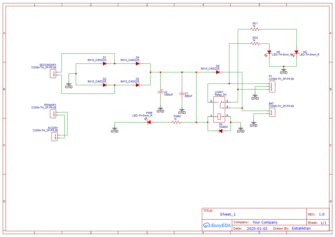
The Mini DC IPS circuit consists of several key sections:
- Bridge Rectifier Section: Converts AC 220V to DC 12V using diodes (6A10). A 1000µF capacitor smooths the DC output.
- Relay Control Section: Uses a 5V SPDT relay to switch between battery and AC input. A 1N4007 flyback diode prevents voltage spikes.
- LED Indicator Section: Three LEDs indicate different statuses: Power LED (system on), NC LED (normal operation), NO LED (relay activated).
- Load & Battery Connections: Clearly marked terminals for DC load and battery, ensuring a secure setup.
- Protection Circuit: Prevents overvoltage, overcurrent, and short circuits for safe operation.
Discover Easy, Affordable, and Reliable PCB manufacturing with JLCPCB!Register to get $60 New customer coupons:https://jlcpcb.com/?from=EST Special Deal: Get a $30 coupon for JLCPCB premium 6-layer PCBs: https://jlcpcb.com/6-layer-pcb?from=getcoupon
Step-by-Step Assembly InstructionsStep 1: Gather All ComponentsEnsure all required parts are available. Use a soldering iron, multimeter, wire cutter, and screwdriver.
Step 2: Set Up the Bridge RectifierArrange the diodes (6A10) in a bridge configuration, solder them properly, and connect them to the AC input. Use a multimeter to verify the DC voltage output.
Step 3: Install CapacitorsConnect the 1000µF and 680nF capacitors to the rectifier circuit. Ensure correct polarity to avoid damage.
Step 4: Connect the Relay and Flyback DiodeSolder the 5V relay and place the 1N4007 diode across its terminals. Ensure proper orientation to prevent relay malfunction.
Step 5: Install LED IndicatorsConnect the three LEDs to their designated positions. Use 1kΩ resistors to limit current.
Step 6: Connect Battery and LoadAttach the battery to the backup power terminals. Connect the DC load (e.g., LED lights, fan) to the output terminals.
Step 7: Test the CircuitPower ON and observe the LED indicators. Verify that the relay operates correctly when switching between AC and battery power.
Step 8: Secure the Circuit on a PCBAfter testing, transfer the circuit onto a PCB to ensure durability and stability.
Common Issues and Troubleshooting- LEDs not lighting up: Check for loose connections or reversed polarity.
- Relay not switching: Ensure the relay coil is receiving the correct voltage.
- No DC output: Verify capacitor connections and diode orientation in the rectifier section.
- Battery not charging: Check the connection between the transformer and rectifier.
Building a Mini DC IPS at home is a rewarding and educational project. By following this guide, you can create a reliable power backup system for your router, LED lights, or other small DC devices. This setup ensures uninterrupted power supply during outages, making it an essential DIY project for home and office use.
Required Components and Specifications- Diodes (6A10) - 5 pieces: Used to convert AC to DC in the rectifier section.
- Capacitors (1000µF, 680nF) - 2 pieces: Smooths the DC voltage output by filtering fluctuations.
- Resistors (1kΩ) - 3 pieces: Limits current flow for the relay and LED indicators.
- Relay (5V SPDT) - 1 piece: Controls automatic switching between AC and battery power.
- LED Indicators (5mm Red LEDs) - 3 pieces: Shows power and relay status.
- Flyback Diode (1N4007) - 1 piece: Protects the relay from voltage spikes.
- Connectors (2P/3P) - 4 pieces: Ensures easy input and output connections.
- PCB Board (Universal or Custom) - 1 piece: Holds all components securely.
- Transformer (AC 220V to 12V) - 1 piece: Converts high voltage AC to 12V DC.
- Battery (12V, 7Ah/10Ah) - 1 piece: Provides backup power when AC fails.
The Mini DC IPS circuit is divided into several functional blocks:
1. Bridge Rectifier Section- Converts AC 220V to DC 12V using diodes (6A10) arranged in a bridge rectifier configuration.
- 1000µF capacitor smooths the DC output by filtering out ripple voltage.
- Uses a 5V SPDT relay to switch between battery and AC input.
- 1N4007 flyback diode protects the relay from voltage spikes.
- 1kΩ resistor limits current to the relay coil.
Three LEDs provide status updates:
- Power LED: Indicates system is active.
- NC (Normally Closed) LED: Shows default relay position.
- NO (Normally Open) LED: Shows when relay is activated.
- Three LEDs provide status updates:Power LED: Indicates system is active.NC (Normally Closed) LED: Shows default relay position.NO (Normally Open) LED: Shows when relay is activated.
- Clearly marked terminals for DC load and battery connections.
- Ensures easy setup and secure connections.
- Prevents overvoltage, overcurrent, and short circuits.
- Ensures safety and longevity of connected devices.
(Insert the circuit diagram image here for reference.)
Step-by-Step Assembly InstructionsFollow these steps carefully to assemble your Mini DC IPS:
Step 1: Gather All Components- Ensure all required parts are available.
- Use a soldering iron, multimeter, wire cutter, and screwdriver.
- Arrange diodes (6A10) in a bridge configuration.
- Solder them properly and connect to AC input.
- Use a multimeter to verify DC voltage output.
- Connect 1000µF and 680nF capacitors to the rectifier.
- Ensure correct polarity to prevent damage.
- Solder the 5V relay and place 1N4007 diode across it.
- Check for proper orientation to avoid relay malfunction.
- Connect LEDs to designated points in the circuit.
- Use 1kΩ resistors to limit current.
- Attach battery to the backup power terminals.
- Connect DC load (e.g., LED lights, fan) to the output.
- Power ON and observe LED indicators.
- Verify relay operation by switching between AC and battery.
- Once tested, transfer the circuit to a PCB for durability.
- LEDs not lighting up: Check for loose connections or reversed polarity.
- Relay not switching: Ensure the relay coil is receiving the correct voltage.
- No DC output: Verify capacitor connections and diode orientation in the rectifier section.
- Battery not charging: Check the connection between the transformer and rectifier.
✔ Router and ONU Backup: Provides uninterrupted power for internet devices.✔ Emergency Lighting: Powers LED bulbs during blackouts.✔ Small DC Appliances: Suitable for 12V fans, small motors, and sensors.✔ DIY Power Supply: Can be used in low-power electronics projects.
Video Reference:Discover Easy, Affordable, and Reliable PCB manufacturing with JLCPCB!Register to get $60 New customer coupons:https://jlcpcb.com/?from=EST Special Deal: Get a $30 coupon for JLCPCB premium 6-layer PCBs: https://jlcpcb.com/6-layer-pcb?from=getcoupon
ConclusionThis DIY Mini DC IPS is an excellent backup power solution for your DC appliances. With a 10A capacity, automatic relay switching, and LED indicators, it provides a stable and efficient power source. By following this guide, you can easily build your own Mini IPS at home with minimal cost.
💡 Let me know if you need any modifications or additional details! 🚀


Comments
Please log in or sign up to comment.