MotivationI'm an undergraduate university student, and for my senior design capstone project, was tasked with being the hardware lead of my year-long autonomous vehicle project, titled "AutoPark." Our goal was to create a self-driving, self-parking full-scale vehicle, and I was in charge of the embedded portion of the project. I decided to take a class on embedded design, ENGI 301, to bolster my knowledge and facilitate my portion of the project. This is my final project in that class.
I had designed a fob-controlled state driver specifically for my senior design project but needed a fun application for it in ENGI 301. I decided on repurposing my model as a remote-controlled lighting system that could be a fun application in houses, dorms, cars, and full-sized golf carts used in autonomous driving projects. A few considerations had to be put in place: I wanted user input, wireless communication, and LEDs for output and debugging purposes. I also considered other meaningful ways to display state data, such as a TFT LCD screen. Unfortunately, some of my parts did not come in on time, so I was unable to install the LED strip lights and fancy LCD screen. Even so, I was able to get my system to work!
Design ProcessI decided on using four tactile pushbutton inputs for four different lighting modes, but you can choose to use more or fewer states and modify the code as you please. These pushbuttons correspond with different LEDs for debugging and visual purposes. I used an Arduino Uno for the sake of simplicity and connected it to an Adafruit RFM69HCW radio transceiver.
The transceiver sends data wirelessly to another RFM69HCW module, which acts as a receiver in this project. It sends data to another Arduino Uno, which takes sends the information to an object detection module and a state driver module.
The object detection module uses three HC-SR04 ultrasonic sensors that detect the distance at which an object is from the sensor. After crossing an adjustable threshold, it'll send a signal through an Arduino to the state driver module.
The state driver module determines which state is being driven based on logic from the receiver and object detection modules using a BeagleBone Black. It outputs this data to some LEDs. (In my senior design project, we are currently working on establishing a connection between the BeagleBone and a Jetson Nano, which is in charge of the machine-learning capabilities of our vehicle. We are also currently working on outputting state data to a touchscreen TFT LCD screen.)
State Driver Block Diagram
In order to make your own remote-controlled lights (with four button states), follow the fritzing diagrams below. You can also download fritzing diagrams in the attachments of this project.
When wiring up the radio modules, remember to attach a wire to the antenna pin. Alternatively, you can purchase a better antenna online. I used a wire, and my system worked perfectly, but if you want a longer range, buying an antenna works really well. I recommend checking the RFM69HCW documentation on the Adafruit website for recommendations.
State driver fritzing diagram
Files for this section of my project are under the 'transceiver' directory of my GitHub repository. They are.ino files, so run them in the Arduino IDE.
Developing Wireless CommunicationFiles for this section of my project are under the 'receiver' directory of my GitHub repository. They are.ino files, so run them in the Arduino IDE.
Fob and receiver displaying state #4
Files for this section of my project are under the 'receiver' directory of my GitHub repository. They are.ino files, so run them in the Arduino IDE. In my documentation, I refer to this part as an 'emergency braking module' for the AutoPark senior design project.
State Driver DesignThe only thing left to do is to wire everything together! Between the BeagleBone Black and the Arduino Uno, the logic voltage is different, so I used a logic level shifter to make the transition safe and easy.
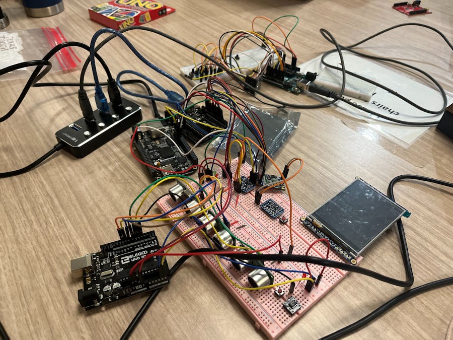
Full system implementation
Receiver/transceiver module
Object detection module (1)
Object detection module (2)
State machine driver


_ztBMuBhMHo.jpg?auto=compress%2Cformat&w=48&h=48&fit=fill&bg=ffffff)


Comments
Please log in or sign up to comment.