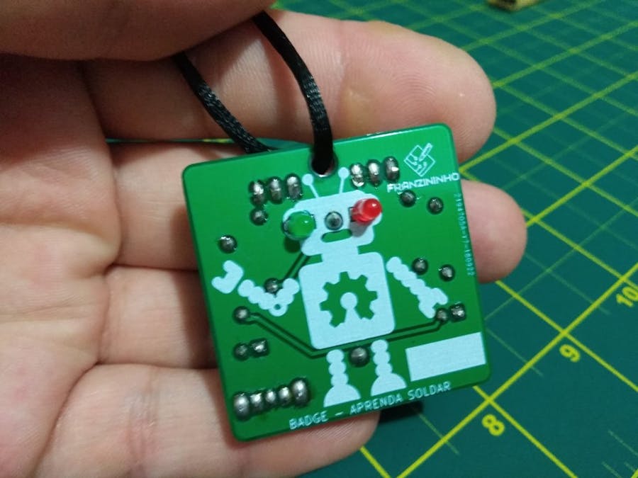
I made several electronics workshops in Brazil with the Franzininho project last year, then I realized the need for a simpler starter board. The badge circuit is an astable oscillator, which was the first circuit I made in my life a long time ago. But the badge has a nice board that everyone wants to solder when they see it. I made the PCB with a robot draw and the LEDs are the robot eyes.
It is part of an initiative I launched here called open badges.
The layout was developed in Kicad and the project is open hardware.
We have already done several workshops in Brazil with this badge:
Bellow, you find all the details of badge hardware.
SchematicThe circuit is quite simple, it is a classic astable oscillator with bipolar transistors. For power, a coin cell battery is used and there is also a power switch.
The following is the bill of materials:
- 2 x Resistor 470k
- 2 x Resistor 470 Ohm
- 2 x BC548
- 1x LED 3mm green
- 1x LED 3mm yellow
- 2 x Electrolytic Capacitors 10uF x 16V
- 1 x Battery Holder for CR2032
- 1 x CR2032 Coin cell Battery
The PCB was designed in Kicad. With two faces is a simple circuit and can be used as a base for beginners in Kicad. Please, make a fork!
Assembly of the board should be done with care, especially by the beginners in soldering. The soldering iron can be dangerous if we touch the wrong part. Be careful if you have never soldered before.
With the board and components in hand perform the soldering in the following sequence:
- Resistors R2 e R3: 47K — colors (yellow, purple, orange and gold)
- Resistors R4 e R1: 470 Ohms — colors (yellow, purple, brown and gold)
- Transistors: Q1 e Q2: BC548
- LEDs - Solder them in the robot eye
- power switch
- Battery Holder
- Electrolytic Capacitors C1 e C2: 10uF x 16V
- And finally, insert the battery into the holder
Congratulations! Now your board is ready to be used as a badge! Write your name in the blank area and show it to your friends
You can buy the PCB Badge at OSH Park: https://oshpark.com/shared_projects/86fSRQDG


_4YUDWziWQ8.png?auto=compress%2Cformat&w=48&h=48&fit=fill&bg=ffffff)


_Ujn5WoVOOu.png?auto=compress%2Cformat&w=40&h=40&fit=fillmax&bg=fff&dpr=2)
Comments
Please log in or sign up to comment.