The Things Network (TTN) is the fasted growing open, crowdsourced network for the Internet of Things. With great use case for cities as well rural areas with now mobile network coverage. Just add your own gateway to the TTN and be part of the global community. Check for details: https://www.thethingsnetwork.org
Now as we all build this growing network, key is to understand how the network coverage grows. Where are white spaces to place a next gateway? How is my gateway performing? What distance I can send data? etc. To answer all this questions there is a great tool call the TTN Mapper https://ttnmapper.org
Now the easiest way to feed to the mapper is the APP on iOS or Android which is paired with one of your sensor nodes. The smartphone provides the GPS data. BUT what do you do if you don't want to have a mapping device being attached to your car or bike... with out the need having your smartphone being close to your sensor node? Just build a tiny GPS tracking node... Here we go:
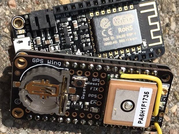
Wire the TX breakout to the PIN0 of the Feather Header - see short, cornered yellow wire in picture. Add the coin cell for backup and fast first GPS fix. Solder the "long" headers to the GPS wing (16 and 12 pins with long pins). On the bottom side your will find solder jumpers for TX/RX just cut them (see adafruit page for reference), as we have now wire TX to an alternate PIN0.
Prepare the LoRa wingFirst of all select the right frequency one for your region (there is 400 and 900 MHz version) - pick the 900 version which is configured in the software to 868 MHz. Adafruit has a great tutorial for all this. Also you will find the length for the cable antenna in this guide https://learn.adafruit.com/radio-featherwing
As the ESP8266 is short on I/O pins and we want to use in addition as well the GPS to receive position data - we do need to wire the LoRa wing in a smart way. Therefore we do need 2x 1N4001 diodes and a short wire.
DIO1 to B with 1N4001 - see orientation of diode in picture above
B to IRQ with 1N4001 - see orientation of diode in picture above
E to CS with WIRE
Solder antenna wire right hand to the receiver module, in my case 8.2 cm
Don't add headers to this wing, it will slide into the GPS module from the buttom, solder the headers from the backside so you have stack as shown.
Prepare the EPS8266 FeatherAdd headers the short if you want to have a compact tracking device, the longer (normal) headers if you want to have space for an optional Feather size LiPo (400mAh).
Flash the software on to the ESP8266 Feather before stacking all together, don't forget to change sampling time and your EUIs of the device you created already in the TTN network (not going in to details here).
Stack all together.
Integration with the TTN Mapper
You do need two more things to be done on the TTN console in your Application configuration. Assuming you have created a device for your mapper (here you get the EUIs!) we need to attach an decoder to the Application assigned to the device:
function Decoder(b, port) {
 var lat = (b[0] | b[1]<<8 | b[2]<<16 | (b[2] & 0x80 ? 0xFF<<24 : 0)) / 10000;
 var lon = (b[3] | b[4]<<8 | b[5]<<16 | (b[5] & 0x80 ? 0xFF<<24 : 0)) / 10000;
 var alt = (b[6] | b[7]<<8 | (b[7] & 0x80 ? 0xFF<<16 : 0));
 var hdop = b[8] / 100;
 return {
     latitude: lat,
     longitude: lon,
     altitude: alt,
     hdop: hdop
 };
}
Copy and paste this decoder into the Payload Format:
Last add the TTN Mapper Integration
If all runs well your should now see valid GPS data under the data tab followed by data ob the TTN mapper. To use see your new mapping device use this link with your data:
https://ttnmapper.org/special.php?node=mapper&date=2019-07-14&gateways=on
node = your device name
date = your mapping date


Comments