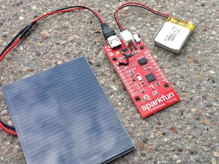
Inspired by the lander #Philae on comet 67P we started a while back working on low-power projects assuming that we do have only solar power to recharge batteries and might need to sleep during a period of time to wake up on a given event.
Update: the project has now proven to run solely of solar power for 3 days/nights, that might sound not that much, but bear in mind we are running an power hungry wifi module just from a 200mAh LiPo and harvesting solar power from a tiny 0.5W solar panel ... as a comparison the used LiPo would ran out of power without any tricks in a single hour. Read about the tricks used:
The ESP8266 Thing from SparkFun is a nice board - but first we want to get it ready for NodeMCU so we can code it in LUA language without the need of an Arduino(TM) IDE. Further more we use LUA to control the sleep mode (switching off not used components) and wake up for work - isn't it like real life ;-) With that we can run the ESP8266 Thing and equivalent ESP8226 (e.g. Adafruit) independent from the power grid just by solar power! Btw. we just add a solar panel and a LiPo - *no* expensive solar charger!
Step 1
Cut the DTR trace on the back of the board for allowing serial debugging and flashing new firmware.
Step 2
Installation of ESP8266 tool chain on Raspberry Pi
Beside the software installation of compiler and tools for flashing the ESP8266 there is also the demand of an appropriate FTDI 3.3V wiring to the ESP8266.
1. ESPtool – python based tool for flashing the ESP8266
wget --no-check-certificate https://github.com/themadinventor/esptool/archive/master.zip
unzip master.zip
cd esptool-master
sudo python setup.py install
2. LUAtool – libs and samples for coding in LUA language
wget --no-check-certificate https://github.com/4refr0nt/luatool/archive/master.zip
unzip master.zip
3. NODEmcu – firmware for the EPS8266 supporting LUA coding
wget --no-check-certificate https://github.com/nodemcu/nodemcu-firmware/archive/master.zip
unzip master.zip
Flash the latest NODEmcu firmware on to ESP8266:
pi@raspberrypi ~/esp/nodemcu-firmware-master/pre_build/latest $ python /home/pi/esp/esptool-master/esptool.py --port /dev/ttyUSB0 write_flash 0x00000 nodemcu_latest.bin
Connecting...
Erasing flash...
Writing at 0x00062000... (100 %)
Leaving...
Done - Firmware is flashed, just reboot before the next step.
Now we download the auto startup LUA script to allow the ESP8266 connection to an access point:
pi@raspberrypi ~/esp/luatool-master/luatool $ python /home/pi/esp/luatool-master/luatool/luatool.py --port /dev/ttyUSB0 --src init.lua --dest init.lua --verbose
Set timeout None
Set interCharTimeout None
Upload starting
Stage 1. Deleting old file from flash memory
->file.open("init.lua", "w") -> ok
->file.close() -> ok
Stage 2. Creating file in flash memory and write first line->file.remove("init.lua") -> ok
Stage 3. Start writing data to flash memory...->file.open("init.lua", "w+") -> ok
->file.writeline([==[print('init.lua ver 1.2')]==]) -> ok
->file.writeline([==[wifi.setmode(wifi.STATION)]==]) -> ok
->file.writeline([==[print('set mode=STATION (mode='..wifi.getmode()..')')]==]) -> ok
->file.writeline([==[print('MAC: ',wifi.sta.getmac())]==]) -> ok
->file.writeline([==[print('chip: ',node.chipid())]==]) -> ok
->file.writeline([==[print('heap: ',node.heap())]==]) -> ok
->file.writeline([==[-- wifi config start]==]) -> ok
->file.writeline([==[wifi.sta.config("SSID","passkey")]==]) -> ok
->file.writeline([==[-- wifi config end]==]) -> ok
->file.writeline([==[wifi.sta.connect()]==]) -> ok
->file.writeline([==[tmr.alarm(1, 1000, 1, function()]==]) -> ok
->file.writeline([==[if wifi.sta.getip()== nil then]==]) -> ok
->file.writeline([==[print("IP unavaiable, Waiting...")]==]) -> ok
->file.writeline([==[else]==]) -> ok
->file.writeline([==[tmr.stop(1)]==]) -> ok
->file.writeline([==[print("ESP8266 mode is: " .. wifi.getmode())]==]) -> ok
->file.writeline([==[print("The module MAC address is: " .. wifi.ap.getmac())]==]) -> ok
->file.writeline([==[print("Config done, IP is "..wifi.sta.getip())]==]) -> ok
->file.writeline([==[-- dofile ("web.lua")]==]) -> ok
->file.writeline([==[end]==]) -> ok
Stage 4. Flush data and closing file->file.writeline([==[end)]==]) -> ok
->file.flush() -> ok
->file.close() -> ok
--->>> All done <<<---
Now we can monitor the NODEmcu console and see output of the LUA script:
pi@raspberrypi ~ $ screen /dev/ttyUSB0 9600
NodeMCU 0.9.5 build 20150214 powered by Lua 5.1.4
lua: cannot open init.lua
>
As the init.lua has not yet started either do an RESET, POWER ON/OFF, or enter dofile(“init.lua”) to execute the script.
NodeMCU 0.9.5 build 20150214 powered by Lua 5.1.4
init.lua ver 1.2
set mode=STATION (mode=1)
MAC: 18-FE-34-9D-B9-2A
chip: 10336554
heap: 17184
> IP unavaiable, Waiting...
IP unavaiable, Waiting...
ESP8266 mode is: 1
The module MAC address is:
Config done, IP is 192.168.2.115
>
Done – ESP8266 is now connected to the access point showing its DHCP IP address.
Step 3
Stream your data to a cloud!
You will find attached an example for the ThingSpeak cloud, but you can change easily to feed data to any preferred server.
Current Optimization:
As the ESP8266 has a combined HF and application processing on a single MCU the Wifi operation take most of the 100+ mA during normal operation, even it is not transmitting any data. Two reduce the power there are two options: switching off the HF part (yes there is LUA command) or putting the ESP8266 (like the lander on the comet) into a deep sleep mode - switching off all components except a timer for waking up the ESP8266: roughly 88uA is the current consumption during deep sleep. A huge difference!
node.dsleep(microSecs);
Example sleeping 60 seconds and waiting on wake up:
node.dsleep(60000000);
That is the trick! You put the ESP8266 Thing into deep sleep for a given period of time and wake it up based in this time. You do need to connect XDP to DTR (best use a jumper). If you do want to wake up the ESP8266 THING while it is in deep sleep from the outside - like an external tigger: DTR to GND should makes this trick - works great!
Sparkfun: "the ESP8266 can't be programmed while the XPD pin is connected to DTR. Make sure you disconnect the two pins before trying to upload a sketch."
Also if your are going to use the serial line to monitor the ESP8266 Thing, make sure you have NOT connected the DTR to the FTDI.
Some further information (external links)
https://www.sparkfun.com/news/1842
http://tim.jagenberg.info/2015/01/18/low-power-esp8266/
http://blog.hekkers.net/2015/02/26/esp8266-in-deep-sleep/
Solar Power
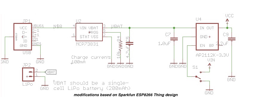
first prototype completed ... R4 to 10K to reduce charing current to 100mA ... add 200mAh LiPo and connect a 5V 100mA solar panel to charge ... make sure the solar panel is not exceeding 6V on max. ... detailed modifications (we take no guarantee, modifications on your own risk!):
If the yellow LED is on in max sun exposure and the red LED goes on if you switch the power on ... all should be working - don't forget to use the deep sleep trick ... otherwise the small amount of solar power and battery are not lasting long!
Power Consumption Tuning
To get really down to the uAs we need to better understand what the ESP8266 is doing ... attached a screenshot of the current data log done with the Keysight N6781A:
Marker (1) is right after power on: avg. 77,2 mA WiFi init an negation with base station starts, followed by probing for DHCP IP address and followed by an http post to the cloud sending a single data frame. Marker (2) is after setting deep sleep mode: avg. 7,8 mA. Peak is 383 mA as of WiFi boost.
Why is the current still high? that is caused mainly by the status LEDs. We are going to disable both LED (charging and power on) in the next step.
The new deep sleep current consumption is 88 uA ! That is cool for now ;-)
Marker (1) is again power on: avg. 72,5 mA with WiFi enabled and Marker (2) shows the new tuned deep sleep current at avg. 88.8 uA. Peak is still 213 mA as of WiFi boost.
The measurement shows a test cycle of 60 sec deep sleep and wake up:
Finally we connect the solar panel to the USB port (max. 6V):
Now we do see the same test procedure again: 60 sec deep sleep followed by short wake up (spikes in the graph above). Wuuuhhh - now you see the current in avg. negative: -4.5 mA that is great because now we can charge back current to the LiPo with an avg. current of 4.5 mA on a sunny day while having an ESP8266 Thing doing is job, with this mode we have more energy than we do need.
Done - We have proven you can run an ESP8266 energy hungry thing with a tiny solar panel and not external power supplies ...
Hang on before you start asking what about night / cloudy days etc - that is up to you:
- use a larger solar panel to charge more current over the day
- less often wake up e.g. once / hr
- transmit data only on daylight
- build a more efficient solar power charger (got max 25 mA of potential 100 mA)
- go with rechargeable batteries that you could drain more than LiPos
- use BLE instead of WiFi (oh that is smart)
- do your tricks ... (add a comment if you like to share)
Rule by thumb (LEDs disabled, R4 = 10k, FET/diode disabled) avg. 12 mA recharging current with the selected solar panel
- avg. 7 mA current of LiPo with wake up every 60 seconds - night
- avg. 5 mA current of LiPo with wake up every 60 seconds - cloudy
- avg. -5 mA current of LiPo with wake up every 60 seconds - sun
- avg. 75 mA current of LiPo without sleep and no solar power but be careful the more data you transmit the more power it will take (>260 mA) - avoid this mode if you want to run off the power grid.
let do some math:
- avg. of 5 mA using an 200 mAh LiPo will last 40 hr with no sun at all
- 14 hrs daylight will charge the LiPo avg. 70 mAh
- 10 hrs night will drain the LiPo avg. 70 mAh
Again use your tricks and tweaks to make it last years ... e.g. having a one wake up only once an hr (compared to every minute) you will reduce the power consumption by a factor >50 ... no data transmission by night (but compute) will drain the LiPo much less.
To achieve a full week day & night test operations solely with solar power - we used an 5 min sleep mode! The backup LiPo had over this period an average load of 70% that give some freedom for cloudy days ;-)
To further make solar power EPS8266 project easy - we started to develop an breakout board for the ESP-12 (e.g. the one from Adafruit) which includes all the latest findings of this project:


_3u05Tpwasz.png?auto=compress%2Cformat&w=40&h=40&fit=fillmax&bg=fff&dpr=2)


Comments