


Hardware components | ||||||
 |
| × | 1 | |||
 |
| × | 1 | |||
 |
| × | 1 | |||
 |
| × | 1 | |||
 |
| × | 1 | |||
| × | 1 | ||||
 |
| × | 1 | |||
 |
| × | 1 | |||
| × | 1 | ||||
| × | 1 | ||||
Software apps and online services | ||||||
 |
| |||||
| ||||||
Hand tools and fabrication machines | ||||||
 |
| |||||
 |
| |||||
In this project, a voltage divider is used as a voltage sensor to measure the voltage output of DC LED and fan. The ADC pin from the STM32F407 microcontroller will read the ADC value from the voltage divider output and convert it to the real voltage value and display it on the LCD.
1. What is a Voltage Divider?A voltage divider is a simple circuit that turns a large voltage into a smaller one. Using just two series resistors and an input voltage, we can create an output voltage that is a fraction of the input. In this project, a voltage divider is used as a voltage sensor by making a voltage reference from a relatively big voltage source. The relatively large voltage biases the active electronic components, amplifier circuits, and so on.
A voltage divider is often used with a potentiometer, an electronic device that is used to design a voltage divider that could have a controlled output voltage. The voltage divider circuit principle consists of a serial circuit made of one or multiple components and connected to an input voltage source.
2. Planning a Voltage Divider circuitA voltage divider involves applying a voltage source across a series of two resistors. You may see it drawn a few different ways, but they should always essentially be the same circuit.
The voltage divider equation assumes that you know three values of the above circuit: the input voltage (Vin), and both resistor values (R1 and R2). Given those values, we can use this equation to find the output voltage (Vout).
This equation states that the output voltage is directly proportional to the input voltage and the ratio of R1 and R2.
In this project, the voltage divider is designed to have 3 Volt output when the input voltage is 15 Volt. This is because the ADC pins of the STM32F407 Discovery microcontroller have 3.3 Volt reference voltage, so the maximum voltage that could be received by the ADC pins must be below 3.3 Volt. In this project, the voltage reference is 3 Volt.
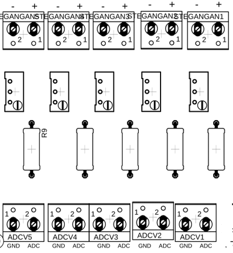
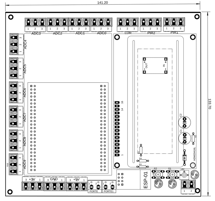
The voltage sensor PCB board is designed by using Autodesk Eagle software and consists of 2 terminals for the input and output, 1k Ω resistor and 1 potentiometer. They are put together in the PCB Board.
An Analog to Digital Converter (ADC) is a very useful feature that converts an analog voltage on a pin to a digital number. By converting from the analog world to the digital world, we can begin to use electronics to interface with the analog world around us.
STM32F407VG6T microcontroller ADC supports 6-bit, 8-bit, 10-bit, and 12-bit configurable resolution. Furthermore, it supports three modes of A/D conversion such as single, continuous, scan, or discontinuous mode. The result of the ADC is stored in the left or right-aligned 16-bit data register. The following table shows the input pins for each analog channel and ADC module.
The ADC resolution can be defined as the smallest input voltage at the analog pin that an ADC can identify and increments its digital value. The maximum and minimum digital output value of ADC depends on the number of bits of the ADC. For example, for an 8-bit ADC, the digital output value will be between 0-255, for a 10-bit ADC, the digital output value will be between 0-1023 and for a 12-bit ADC, the digital output value will be between 0-4095.
ADC resolution can be defined as:
Resolution = ( Operating voltage of ADC ) / 2^(number of bits ADC)
For example, the operating voltage of the STM32F4 series microcontroller is 3.3V and if we configure the ADC in 12-bit mode:
Resolution = 3.3V/2^12 = 3.3/4095 = 0.8mV
STM32CubeMX is a graphical tool that allows a very easy configuration of STM32 microcontrollers and microprocessors through a step-by-step process. In this project, we use the STM32CubeMX to assign ADC Pins on the microcontroller. We also use DMA.
Every measurement system must be proven reliable in measuring, this verification procedure is called calibration. Calibration can reduce errors and improve measurement accuracy. The calibration procedure step uses a comparison of the instrument to be calibrated with a standard instrument.
The voltage sensor calibration testing is done by giving the voltage divider input supply from the DC Power Supply. The output of the voltage divider will be sent to the ADC (Analog-to-Digital) microcontroller pins. The input supply and the output supply of the voltage divider will be measured by digital multimeters.
In this project, the voltage sensor calibration testing shows good results with a small error percentage value within 0.089% - 1.6%. This shows that the voltage sensor can work well. The error percentage value between the ADC value that is calculated based on theory and the ADC Value read from the LCD is relatively small, between 0% - 2.39%.
The picture below shows the comparison between the input voltage and the output voltage testing graphic.
By finding the linear function between the output voltage and ADC, we can use the linear function to convert the ADC value to be the voltage value that will be read by the microcontroller. The linear function obtained is y = 0,00361208999745770x - 0,03304734834610130.
The function is put inside the microcontroller program, and then the error percentage between the voltage divider reading from the multimeter and the LCD and be calculated.
From comparing the voltage value reading from the LCD and the multimeter, It could be concluded that voltage sensor 1 has an error percentage value below 1.6%.
8. Reading DC LEDs and DC Fans Voltage ValueAfter doing the voltage sensor calibration testing, we can finally use the sensor voltage for measuring DC LEDs and DC fans' voltage values. To read the DC LEDs and DC fans' voltage values, connect their outputs to the inputs of the voltage sensors.
A voltage divider is often used as a voltage sensor to measure DC voltage. In this project, we have successfully created a voltage divider as a DC voltage sensor for measuring DC LEDs and DC fans.
Sourceshttps://learn.sparkfun.com/tutorials/voltage-dividers/all
https://learn.sparkfun.com/tutorials/analog-to-digital-conversion
https://www.st.com/en/development-tools/stm32cubemx.html
http://elektronika-dasar.web.id/kalibrasi-alat-ukur-listrik-arus-searah-dc/


Comments
Please log in or sign up to comment.