
Hardware components | ||||||
 |
| × | 1 | |||
_ztBMuBhMHo.jpg?auto=compress%2Cformat&w=48&h=48&fit=fill&bg=ffffff) |
| × | 1 | |||
 |
| × | 1 | |||
| × | 1 | ||||
| × | 1 | ||||
| × | 1 | ||||
 |
| × | 1 | |||
| × | 1 | ||||
 |
| × | 1 | |||
| × | 1 | ||||
 |
| × | 1 | |||
Software apps and online services | ||||||
 |
| |||||
Hand tools and fabrication machines | ||||||
 |
| |||||
 |
| |||||
 |
| |||||
Have you ever used a vortex mixer in your laboratory? It is an handy tool used to mix solutions. When you get used to it you will use it every time you can without regrets.
Since this kind of device is quite expensive but it is not strictly necessary inside a laboratory, I decided to make my own version. By following this guide you will learn how to make your own version too. I hope you will enjoy this reading.
Breadboard prototypeI will start saying that, even if the part list is quite long, this device can be built with things found around, if you look for spare part in broken objects you will find most of the component needed without spending money.
The device can be schematized as follow.
We will use a vibrating motor in order to vortex a sample of our interest. The vibration will start only if we hold a sample onto the motor. This kind of recognition will be achieved with a piezo sensor. Once a pressure is revealed an analog signal controlled by a rotary potentiometer will be sent to the motor driver and thus it will vortexing our sample.
The first thing we want to do is preparing our Arduino on a breadboard and connect the piezo sensor in order to be sure that this guy will work (figure 1)
Figure 1. schematic of the arduino with piezo sensor for pressure detection.
NOTE: you can use both UNO or Nano, I used UNO for breadboard testing and then I made the real prototype using Nano.
In order to make this sensor work really few lines of code are necessary (figure 2).
#define PRESSURE A0
[...]

void pressure_baseline (int *baseline);

[...]

int baseline = 0;
int *ptr_baseline = &baseline;

void setup() {
 [...]
 pressure_baseline(ptr_baseline);
}
[...]
void pressure_baseline (int *baseline) {
 for(int i = 0; i <10; i++){
   *baseline = *baseline + analogRead(PRESSURE);
   delay(500);
   if (i == 9){*baseline = *baseline/10;}
   }
 }
Figure 2. Code necessary for sensor base value calculation.
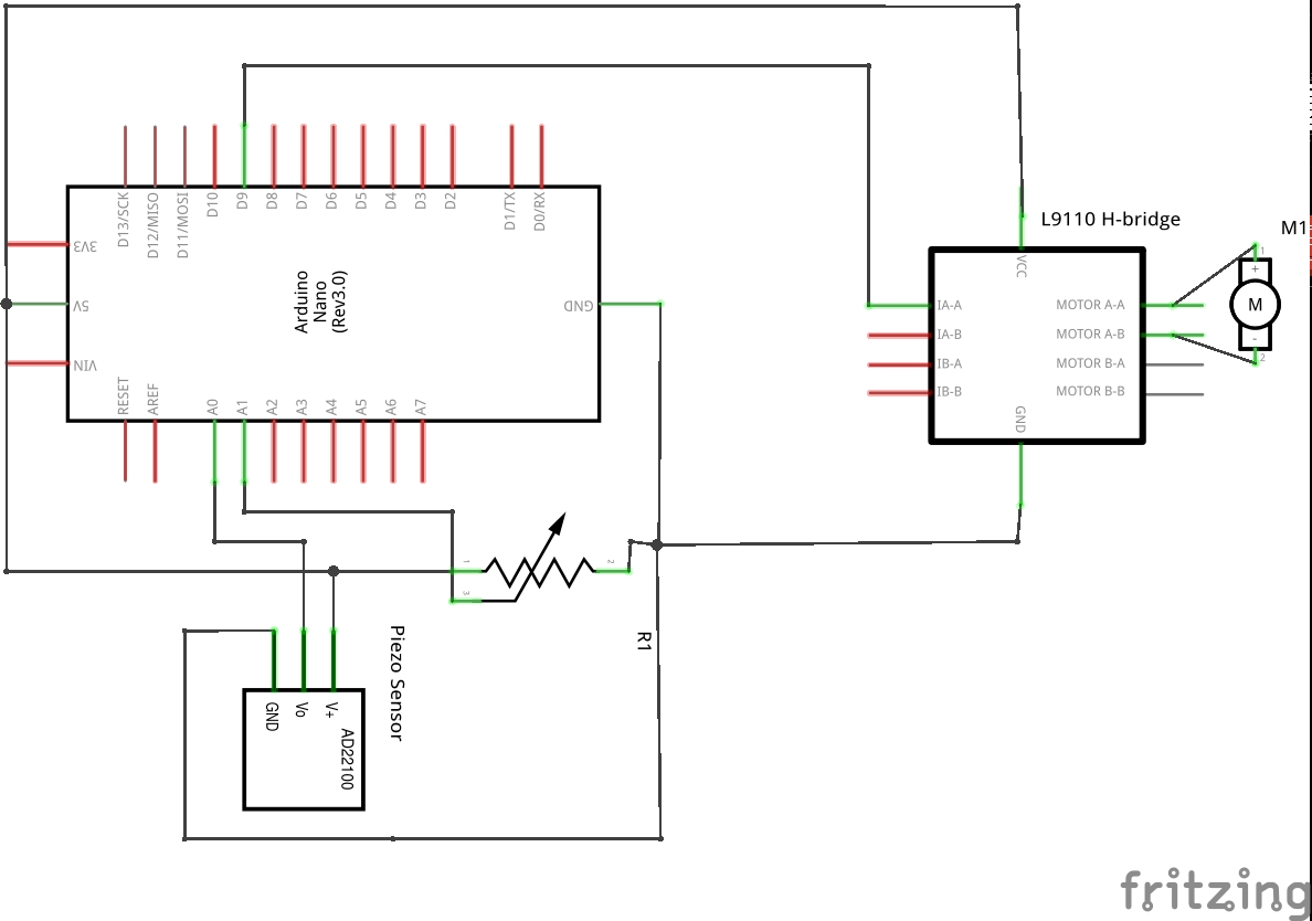
In order to avoid differences in the response of the piezo sensor at rest at each powering of the device and among sensors (I had three sensors giving different values at rest!), the code call the baseline calculation function. This lines calculate the mean of ten values of piezo sensor and this will be used as threshold for pressure detection. Another piece of hardware you will need is the motor and its controller. Figure 3 shows the wiring you will need to set it up. We can't wire directly the motor to a digital pin due to the maximum current output this would supply (20-40mA max depending from the board you are using), but the 5V pin is capable of supplying up to 500mA, which is enough for the vibrating motor!
A potentiometer was also added in order to control the vibration speed.
Figure 3. Schematic of the system with vibrating motor and controlling board.
The code is then modified in order the make the motor work as a function of the of the pressure applied with your sample (figure 4).
#define POTMETER A1
#define MOTORPIN 9
#define ten_to_eight(x) (map(x, 0, 1023, 0, 255))
[...]
void pressure_check (int *baseline);
int *motor_speed (void);
void speed_control (int *speed);
void baseline_drift (int *baseline);
[...]
int counter = 0;
int speed = 0;
void setup() {
 pinMode(MOTORPIN, OUTPUT);
 [...]
}
void loop() {
 pressure_check(ptr_baseline);
 baseline_drift(ptr_baseline);
}
[...]
int *motor_speed (void){
 speed = analogRead(POTMETER);
 speed = ten_to_eight(speed);
 return &speed;
 }
void motor_control (int *speed){
 analogWrite(MOTORPIN, *speed);
 counter++;
 }
void pressure_check (int *baseline) {
 if (analogRead(PRESSURE) > (*baseline + 10) && counter < 20){
   while(counter < 20){
     int *speed = motor_speed();
     motor_control(speed);
     delay(500);
     }
   } else if (counter > 19) {
     analogWrite(MOTORPIN,HIGH);
     delay(1000);
     counter = 0;
     }
 }
void baseline_drift (int *baseline){
 if ( millis() % 3600000 == 0 && counter == 0){pressure_baseline(baseline);}
 }
Figure 4. Code for motor control.
Lets take a closer look to the code and what it does. First you will need to define the motor and potentiometer pins needed and to set the motor pin as output (figure 5).
#define POTMETER A1
#define MOTORPIN 9

void setup() {
 [...]
 pinMode(motorPin, OUTPUT);
 [...]
}
Figure 5. Initialization code.
The rest of the code actually control how the system behave. Four functions are needed. It starts calling pressure_check(), this function check if there is pressure on the piezo sensor and if the answer is positive in calls motor_speed(). This will calculate the output for the motor pin from the potentiometer, a macro function ten_to_eight will map the value for the eight bit output (with a maximum of 180 in order to avoid a massive slowdown of the motor). The last part needed is motor_control() to activate the motor. A counter variable is increased every 0.5s up to a total of 10s then the system stop for 1s and wait for further pressure for a new cycle. A final function baseline_drift() will work every hour and calculate a new base value for the piezo sensor, thus avoiding drifts.(figure 6).
void loop() {
 pressure_check(ptr_baseline);
 baseline_drift(ptr_baseline);
}
[...]
int *motor_speed (void){
 speed = analogRead(POTMETER);
 speed = ten_to_eight(speed);
 return &speed;
 }
void motor_control (int *speed){
 analogWrite(MOTORPIN, *speed);
 counter++;
 }
void pressure_check (int *baseline) {
 if (analogRead(PRESSURE) > (*baseline + 10) && counter < 20){
   while(counter < 20){
     int *speed = motor_speed();
     motor_control(speed);
     delay(500);
     }
   } else if (counter > 19) {
     analogWrite(MOTORPIN,HIGH);
     delay(1000);
     counter = 0;
     }
 }
void baseline_drift (int *baseline){
 if ( millis() % 3600000 == 0 && counter == 0){pressure_baseline(baseline);}
 }
Figure 6. Loop code and functions definitions.
In figure 7 is shown the device assembled on a breadboard.
Figure 7. Device on a breadboard.
As you can see I did put the pressure sensor between two anti static foam sheets. So the motor will not stand directly on the sensor and neither this will stand directly on a rigid surface. Some glue was used to fix the rubber crutch to the motor head. This piece of rubber will be used as sample support while the vibration is on. This will avoid any contact metal/glass (in case you are using a glass container for your sample to be mixed).
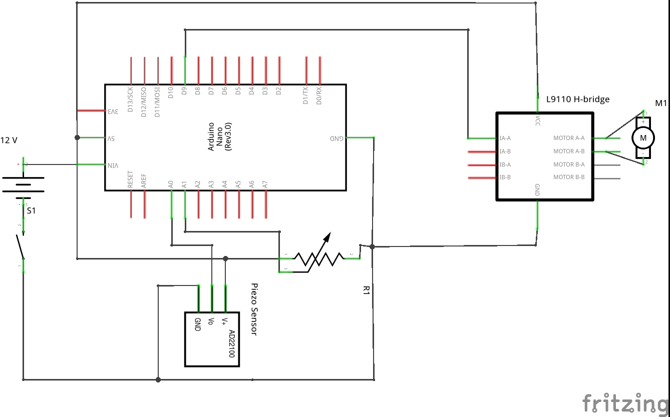
And for the final touch you will need to add a switch and a power supply to your device and turn on your 3D printer (figure 8).
Figure 8. Schematics with power supply and switch.
EDIT: NOTE if you use an external supply of 12V could be a good idea to use a voltage converter to supply 5V instead of 12V. This is important since we use the 5V pin to supply current to the vibrating motor. The internal regulator may overheat fast and blow your board!
Real prototypeLets now move on to the real prototype. For this part you will need to print the three necessary pieces. Figure 9 shows them, you can find the .obj files at the end of the page.
Figure 9. 3D components for vortex prototyping.
The assembly part of this tutorial is pretty straight forward. Your will need to position all the electronic component in the base. Probably a glue gun will be necessary in order to fix all the component and avoid unnecessary movement. In the central part will be fixed the anti-static foam. Figure 10 shows the base component with every component fixed with glue.
Figure 10. Prototype base.
As you can see a female jack for 12V power supply was added and soldered to the Vin pin and ground. If you don't have one of those you can always cut the wires of the supplier and use the bare wires. However this way is not clean and thus not suggested!
For the final touch just grub a couple of screw and fix the motor to the base. Plug in your 12V supply and you are ready (figure 11).
Figure 11. Complete device.
And we are done. The final device is complete and ready to use. You can further customize your device by adding some weight to the base part if the vibration is too strong in order to avoid the device movement!
I hope you enjoyed building with me this useful device for everyday life in laboratory.
See you in the next tutorial.
Vortexer schematics without external power


Comments