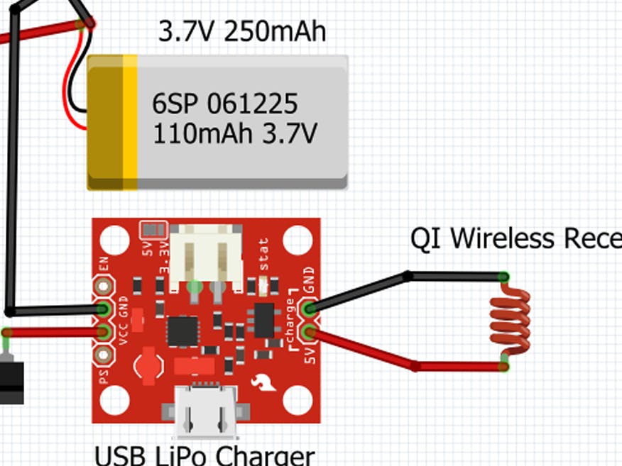
I was working on a project and got taken with the need of charging "in place" a small form factor LiPo battery (3.7V 250mAh). FIRST - It was important that I could know the charge state to decide when to re-charge and understand the power consumption profile. SECOND - This battery are dangerously risky (!!!) to charge and a compact project (small case) is quite difficult to disassemble every time. The SOLUTION, with the help of several dedicated people on the FORUM, was to assemble a BATTERY TESTER and a sketch to run it. To charge the battery I decided to insert a switch to commute the battery to a QI wireless charger through a USB charger circuit that I had to modify to adapt to the low current needed.
It is important to understand that this "snippet" can be inserted in any project you like, just like I did with mine. Try it on a breadboard with any battery you have and then move on (I enclosed a test sketch for the experiments).
So. We will connect the Li-Ion battery to the Arduino (3.3V) VIN pin, though it has a maximum charge value of 4.2V. Using the RAW pin is not necessary.
First of all. The Arduino boards ADC would measure a voltage applied to one of the analog pins BUT if you try to measure the voltage that you supply to the Arduino VIN this is "auto-referential". You need to use a function called analogReference() to set the ADC to work with an INTERNAL voltage, regulated and taken from the microprocessor, that will always be 1.1V so that, when the battery inevitably starts to lower its voltage, the comparison value shall be stable. This causes a problem, if the 0-1023 range has a maximum of 1.1V and your battery is about 4V you have to lower the input voltage. How? With a "voltage divider" (you can find many references if you want to understand it better). The V D is a very simple circuit made with just two resistors (values can be calculated here - the higher the better for power consumption!).
Now that we have a way to lower our maximum battery voltage under 1.1V we can make a measure. The percentage of how FULL is the battery can be used within a if clause to display three different battery graphic icons of the different levels of charge (see following sketch and documentation on analogReference()).
The second part of this project was added because, when you read that the battery needs charging, you would need to take it out and connect it to a LiPo charger (not any charger!!). I found that a very small form factor charger can be connected via a two way switch (one side will power the Arduino - the other will get the LiPo charged). As INPUT to the charger circuit I also connected a QI wireless receiver so that when you put your "case" on any standard smartphone wireless charging unit (transmitter - I have an old one fm Nokia and another cute FatBoy) it will get the power it needs to charge. PAY REAL ATTENTION to the current needed (which is 40% of the nominal capacity of the battery). The factory setup of the charger (for smartphones!) is 1A, way too much!!! A table is provided with the documentation with values of a particular resistor, shown, that can be changed to get the mAh you need. This mod needs some specific ability and good eyes as the SMD resistors are VERY SMALL. (you can find a lot of information online on how-to to this). PLEASE do not use ONE FULL AMPERE to charge a micro-battery!!!
You obviously can adapt the tester to work on a breadboard with Arduino UNO and any battery - the enclosed sketch does just that. If you use a PRO MINI you should know that you need an adapter to connect to the PC to upload the sketches. I am not very advanced and was able to do it all with just a little of study, the help from the FORUM and patience.
INSPIRATIONs for follow-up improvements (keep me posted!)...
- using an optocoupler to switch the battery to charge
- using diodes and MosFET (?)... (advice from the Forum)


_ztBMuBhMHo.jpg?auto=compress%2Cformat&w=48&h=48&fit=fill&bg=ffffff)


Comments
Please log in or sign up to comment.