Follow your child's growth with a digital stadiometer!
During my childhood, my mother was used to periodically take my height and write it down on a block notes to follow my growth. Of course, not having a stadiometer at home, I was standing against the wall or the door jamb while she took the measure with a tape. Now I have a newborn grandaughter and when she starts walking, her parents will certainly be interested in following her growth in height. So, the idea of a digital stadiometer was born.
It is made around an Arduino Nano and a "Time of Flight" sensor which measures how long the tiny laser light takes to bounce back to the sensor.
Step 1: Parts and Components- Arduino Nano Rev 3
- CJMCU 530 (VL53L0x) laser sensor
- KY-040 rotary encoder
- SSD1306 OLED 128x64 display
- Passive buzzer
- 2x10KΩ resistors
The ST Microelectronics VL53L0X is a new generation Time-of-Flight (ToF) laser-ranging module housed in a tiny package, providing accurate distance measurement whatever the target reflectances unlike conventional technologies.
It can measure absolute distances up to 2m. The internal laser is totally invisible to the human eye (wavelenght 940 nm) and complies with the latest standard in terms of safety. It integrates an array of SPADs (Single Photon Avalanche Diodes)
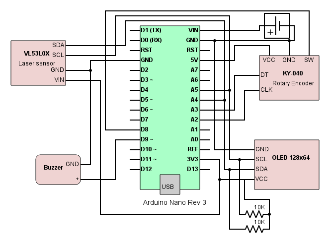
Communicating to the sensor is done over I2C. As the project includes also another I2C installed (the OLED), 2 x 10KΩ pullup resistors are needed on the SCL and SDA lines.
I have used the CJMCU-530, which is a breakout module featuring the VL53L0X by ST Microelectronics.
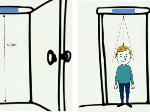
Step 3: Operations and Sensor PositioningOnce built and tested, the device should be mounted on the center of a door frame top; this is because if you mount it too close to a wall or an obstacle, the IR laser beam will be interfered and create a crosstalk phenomenum on the measure. Another option would be to install the device through an extension rod to move it away from the wall, but it is more inconvenient.
Carefully take the correct lenght measure between floor and the sensor (offset to be set) and calibrate the device (see next step). Once calibrated, the device can be used without need to calibrate again, unless you move it into another position.
Switch on the device and place yourself below it, in a straight and firm position. The measure will be taken when the device detects a steady lenght for more than 2.5 seconds. At that point it will emit a "success" music sound and keep the measure held on the display.
Step 4: Offset CalibrationAs mentioned before, you need to set the correct value (in centimeters) for the offset, the distance between the measuring device and the floor. This can be achieved by pressing the rotary encoder knob (which has a pushbutton switch). Once activated the calibration mode, set the right distance by rotating the knob (clockwise adds centimeters, counterclockwise subtracts). Offset ranges from 0 to 2.55 m.
When done, just press the knob again. Two different tones will be generated by the internal buzzer to give you an acustic feedback. The calibration mode has a timeout of 1 minute: if you don’t set the offset within this timeout, the device exits from calibration mode and falls back to measuring mode, without changing the stored offset. The offset is stored into Arduino’s EEPROM memory, to keep it through subsequent shutdowns.
Step 5: CodeST Microelectronics has released a full API library for the VL53L0X, including gestures detection. For the purpose of my device, I have found easier to use Pololu's VL53L0X library for Arduino. This library is intended to provide a quicker and easier way to get started using the VL53L0X with an Arduino-compatible controller, in contrast to customizing and compiling ST's API for the Arduino.
I have set the sensor in HIGH ACCURACY and LONG RANGE mode, in order to have more freedom on installation height and offset setting. This will result in a slower speed of detection, which is anyway enough for the purpose of this device.
The offset is stored in Arduino's EEPROM memory, whose values are kept when the board is turned off.
In the loop section, the new measure is compared with the previous one and if 2.5 seconds are passed on the same measure (and if it is NOT an Offrange or Timeout value), the measure is subtracted from the offset and steadly shown on the display. A "successful" short music is played by the piezo buzzer, to aurally notify the user.
Step 6: SchematicsAs my inability to cut rectangular windows on commercial boxes is very well known, I took the path to design a case with a CAD and send it for 3D printing. It is not the cheapest choice, but it is still a convenient solution because it offers the possibility of being very precise and flexible on the positioning of all the components.
The small laser chip is mounted without any cover glass, in order to avoid crosstalk and erratic measures. If you want to install the laser behind a cover, you'll need to undertake a complex calibration procedure as reported in ST Microelectronics' documentation.


Comments
Please log in or sign up to comment.