Measurino simply counts the number of rotations of a wheel and the distance travelled is directly proportional to the radius of the wheel itself. This is the basic principle of an odometer and I have started this project mainly to study how to keep the circuit (handled by an Arduino microcontroller), compatible with several range of distances, from millimeters to kilometers, and to evaluate possible problems or improvements.
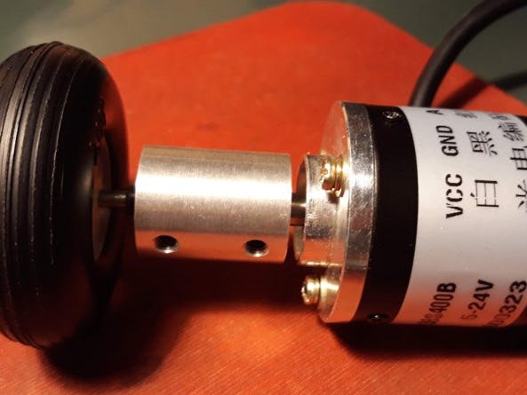
The EncoderFor this project I have tested several cheap rotary encoders, but I immediately discarded them due to precision/sensitivity issues. So I went to the DFRobot’s Incremental Photoelectric Rotary Encoder – 400P/R SKU: SEN0230. This is an industrial incremental photoelectric rotary encoder with aluminum material, metal shell and stainless steel shaft. It generates AB two-phase orthogonal pulse signal through the rotation of the grating disk and optocoupler. 400 pulses/round for each phase, and 1600 pulses/round for dual-phase 4 times output. This rotary encoder supports max 5000 r/min speed. And it can be used for speed, angle, angular velocity and other data measurement.
The photoelectric rotary encoder has a NPN open collector output, so you need to use pullup resistors or enable the internal Arduino’s pull-up. It is using 750L05 voltage regulator chip, which has a DC4.8V-24V wide range power input.
SensitivityThis optoelectric rotary encoder has really a great sensitivity, which makes it perfect for shaft-controlling and positioning applications. But for my purpose it was too much sensible. With a 51mm wheel, this encoder has a sensitvity of 0.4mm, which means that if you hand has minimal trembles, they will be recorded. So I lowered the sensitivity by adding an hysteresis in the interrupt routine:
void interrupt()
{
  char i;
  i = digitalRead( B_PHASE);
  if (i == 1)
    count +=1;
  else
    count -=1;
  if (abs(count) >= hysteresis)
  {
    flag_A = flag_A+count;
    count = 0;
  }
}
This trick was enough to give a good stability to the measure.
MeasurementSelect your Unit of Measure (Decimal or Imperial) and then just position the wheel with its contact point on the start of your measure, press the Reset pushbutton and keep it rotating until the end. From left to right the measure increase and sums up, for right to left it decrease and subtract. You can measure also curve objects (your car shape, the handrail of a spiral staircase, the lenght of your arm from the shoulder to the wrist with the elbow bent, etc.).
A full rotation of a wheel with diameter=D will measure a lenght of D*π. In my case, with a 51mm wheel, this is 16, 02cm and each tick measures 0.4mm (see Sensitivity paragraph).
AssemblingThe PoC has been made on a breadboard to demonstrate the circuitry. Every component has been attached on the board and the rotary encoder is connected to a 2×2 Pole Screw Terminal Block. The battery is a 9v standard battery and the total power consumption of the circuit is around 60mA.
The CodeFor the display, I used the U8g2lib which is very flexible and powerful for this kind of OLED displays, allowing a wide choice of fonts and good positioning functions. I didn’t waste too much time in filling up the display with informations, as this was just a Poc. To read the encoder, I am using interrupts generated by one of the 2 phases: each time the encoder shaft moves, it generates an interrupt to Arduino tied on the rising of the impulse.
attachInterrupt(digitalPinToInterrupt( A_PHASE), interrupt, RISING);
The display automatically switches from millimeters, to meters, to kilometers and (if selected from the pushbutton) from inches, to yards, to miles, while the RST pushbutton resets the measure to zero.
From PoC to production!Why is this a Proof of Concept? Beacuse of many improvements that could/should be done before building a full functioning equipment. Let’s see all of possible improvements in details:
- Wheel. The sensitivity/precision of Measurino is depending upon the wheel. A smaller wheel could give you better precision in measuring small lenghts (in the order of millimeters to centimeters). A much larger wheel with an extension boom will allow to walk on the road and measure kilometers. For small wheels, the material has to be considered: a full-rubber wheel could slightly deform and affect the precision, so in that case I will suggest an aluminium/steel wheel with just a thin tape to avoid slips. With a trivial software edit (select the correct wheel diameter with a switch), you could consider interchageable wheels to adapt to any measure, by using a 4-pin connector (i.e.: usb port).
- Software. By adding another pushbutton, the software could also take care of measuring areas of rectangles or angles amplitude. I also advise to add a “Hold” pushbutton to freeze the measure at the end, avoiding to inadvertently move the wheel before reading the value on the display.
- Replace the wheel with a spool. For short measures (within few meters) the wheel could be replaced with a springed spool containing thread or tape. In this way you just need to pull the thread (making the encoder shaft rotate), take your measure and watch at the display.
- Add display of battery state. The 3.3v Arduino reference pin (accurate within 1%) can be used as a base for the ADC converter. So, by doing an analog to digital conversion on the 3.3V pin (by connecting it to A1) and then comparing this reading against the reading from the sensor, we can extrapolate a true-to-life reading, no matter what VIN is (as long as it’s above 3.4V). A working example could be found in this other project of mine.
Image Gallery


_3u05Tpwasz.png?auto=compress%2Cformat&w=40&h=40&fit=fillmax&bg=fff&dpr=2)
Comments
Please log in or sign up to comment.