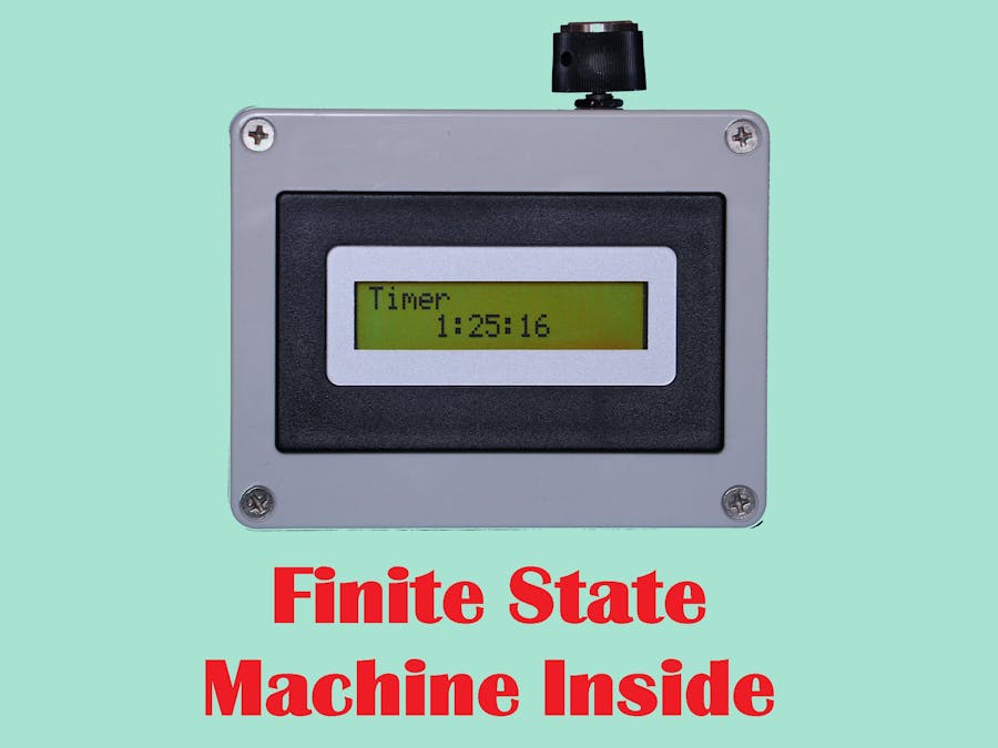
This project explains how a finite state machine may be useful to make a user-friendly interface with an alphanumeric display and a rotary encoder. As an example we will realize a simple timer, but you will be able to create your own machines easily.
HistoryI wanted to put several devices into the same box. In this box I connected an Arduino Nano Every with a 2 x 16 characters LCD (Liquid Crystal Display), a rotary encoder, a RTC (Real Time Clock), a beeper and a temperature and pressure measuring module. And now, by turning the rotary encoder, I can access a clock and calendar, a thermometer and barometer, a tide clock, a timer and so on... By pushing the rotary encoder, I can adjust many parameters: the temperature unit (°C, °F or °K), the pressure unit (mmHg or hPa), the altitude which is used to calculate the pressure at sea level, the brightness of the LCD...
The Arduino board is behind a hole of the box, so I can connect it to my PC and program it without opening the box. So I create and add new devices but I never open the box. Today I have opened it exceptionally just to photography it and show you what is inside.
I will not put this project into the project hub because it is not finished, and I think it will never be. Instead, I will explain how to do a simple device (a timer) using the same techniques, essentially the user interface based on the LCD, the rotary encoder and a finite state machine. Afterwards, you will be able to use the program as a frame to realize your own projects and to make very complex machines.
User manual of the timerTo use this timer, you program a delay by pressing the rotary knob during more than 3 seconds. You choose the number of hours, the number of minutes and the number of seconds by turning and pressing the rotary knob. Then the timer starts and you can see the delay decrease on the LCD. When the delay reaches 0, the timer beeps. You can stop the beeper by pressing the rotary knob.
This is very simple, so we can add some functions, just for the exercise. First, if you turn the rotary knob, you can see and adjust the brightness of the LCD. If you keep turning the rotary knob, you can see and adjust the tone of the beeper while hearing it. The last function is a pause in the timer countdown: if you press the rotary knob while the timer is running, the counting is suspended. It will restart when you press the rotary knob again.
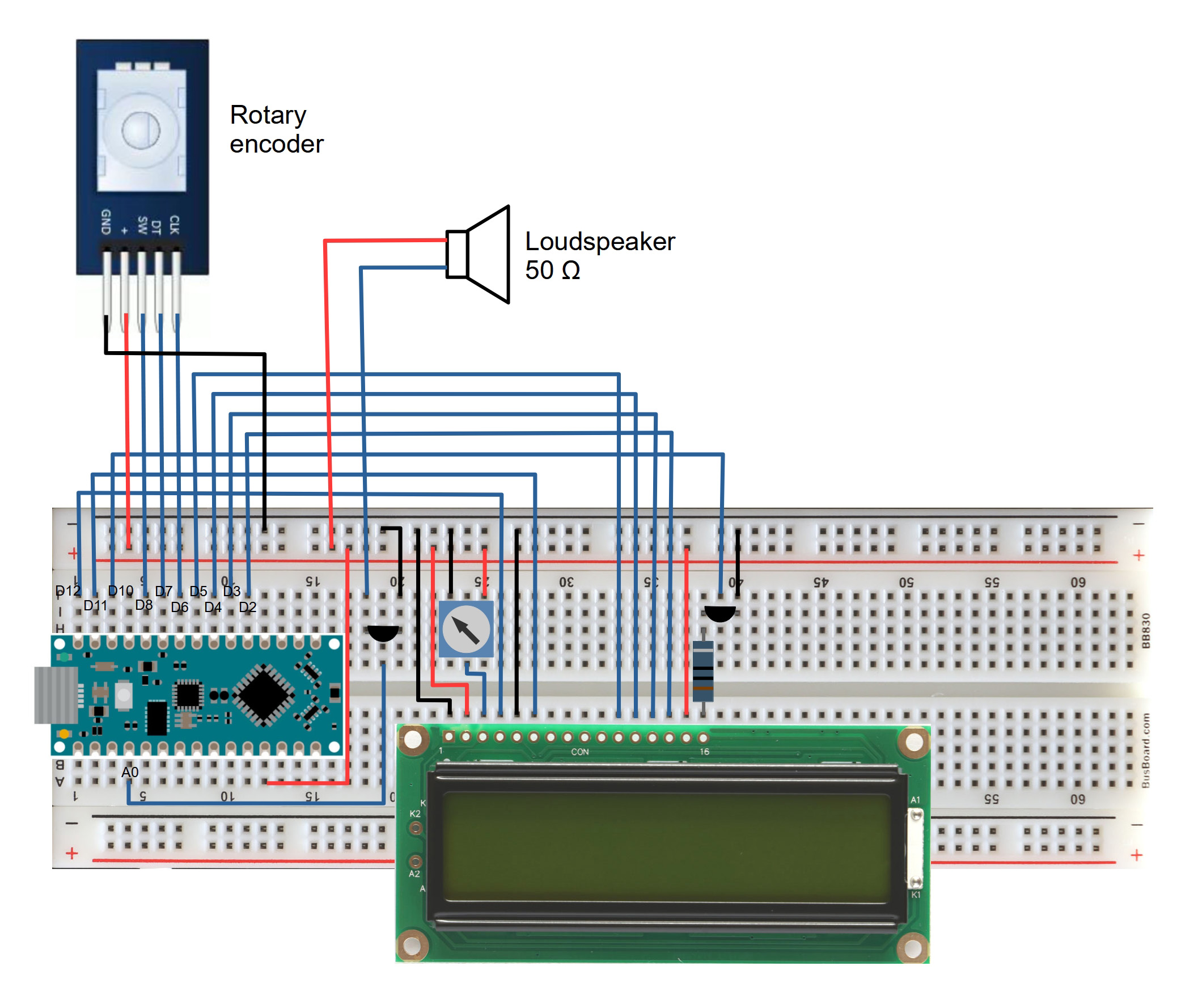
The hardwareI programmed this timer in my box which contains all the necessary hardware, but you can use a breadboard to make your own timer. You will need an Arduino board (I have got a Nano Every, but any board can be used), a standard 2 x 16 alphanumeric LCD with a back-light, a 10 kΩ potentiometer to adjust the contrast of the LCD, a rotary encoder, a beeper, an N-channel FET (2N7000 or equivalent) and a resistor to drive the back-light of the LCD.
The LCD will be connected to the Arduino board in the same manner as in the examples of the LiquidCrystal library. The 10 kΩ potentiometer delivers an adjustable voltage to the V0 input.
The pins CLK, DT and SW of the rotary encoder will be connected respectively to pins 6, 7 and 8 of the Arduino. In my rotary encoder, the pins CLK and DT have an integrated pull-up resistor, while the SW pin does not. So, the pinMode of pins 6 and 7 is INPUT, and it is INPUT_PULLUP for pin 8.
As a beeper, any type of speaker may be suitable. I am using a 50 Ω miniature loudspeaker driven by an N-channel FET. If your loudspeaker has a smaller resistor, you may need to add a resistor in series with it.
The softwareThis project aims to show how we can use a Finite State Machine (fsm) to build a user-friendly interface with a rotary encoder and an alphanumeric LCD. So we will begin by some words about fsm.
In an fsm, there are a number of states, and at any time, the system is in one of these states, called the current state. Events can happen, and change the current state. These changes are called transitions. You can describe the system by a state diagram where all the states and all the transitions are represented. If you want to know more about fsm, you are encouraged to look at the very good project "Using Finite State Machines" by Gustavo. You can access this project by clicking here.
As we are creating a user interface, it is logical to imagine that the current state of the system will change when the user manipulates the rotary encoder. So the events that will make the current state change are issued from the rotary encoder and they can be:
- clockwise rotation (cwRot),
- counterclockwise rotation (ccwRot),
- pushing the switch briefly (shortSwitchPress),
- pushing the switch more than 3 seconds (longSwitchPress),
- nothing happened since 30 seconds (timeOut)
In our timer, there are 8 states. They are represented in the following state diagram with the transitions between them:
Not easy to read? Let me help you.
Progressive construction of the state diagramFirst, let's consider only the three states which display a parameter:
Each of these states displays a different parameter: the remaining time of the timer (timerDisplay), the brightness of the LCD (dimmingDisplay) and the frequency of the beeper (toneDisplay). The transitions between these states are activated by the events cwRot and ccwRot, i. e. the user changes the displayed parameter by turning the rotary encoder.
The timerDisplay state is represented in red to show that it is the initial state at power up.
You can imagine that these states are on a circle and that you travel on this circle when you turn the rotary encoder in one direction or the other:
In our timer we have only three states on the circle, but we could have any number of states. This is very important, because it is the way to expand your system. For each function or device you want to add to your system, you add a new state on the circle. And if there are too many states on the main circle, you can add other circles and put states on them to communicate between circles. (for example a state "System" on the main circle to give an access to a second circle whose states are used to adjust system parameters).
And now, from each state which displays a parameter, we will add a transition towards a state which allows the user to adjust this parameter. These transitions will be activated by a long press on the rotary encoder:
Once the user has adjusted a parameter, he returns to the corresponding display state by pressing briefly the rotary encoder. There is an exception: after setting the hours of the timer delay, he has to adjust the minutes then the seconds. So we will add two new states, and the transitions between them will also be activated by a short press on the rotary encoder:
And now, we will add a special transition. When this transition is activated, the system goes from the timerDisplay state to the timerDisplay state. No, the current state does not change:
This transition is activated when the system is in the timerDisplay state, and the user presses the rotary encoder briefly. Its role is to call a function which positions a boolean. This boolean changes the behavior of some other functions. This way, the user can pause or restart the count when the timer is active, or stop the beeper when the timer has reached 0. Simple, but very powerful.
To terminate, we will add four transitions which are not mandatory, it is just the final touch. Imagine that you are adjusting the frequency of the beeper (the beeper beeps during this operation), and your phone rings. When you are back, the beeper is still beeping. That is not a good idea. So we will stop it automatically after 30 seconds. To do that, we add a transition which is activated by the timeOut event, and which returns from the setting state back to the display state of the beeper frequency. We will do that for all the setting states except one: the timerSecondSet state because if we stop this state automatically, the timer will start. When the user is setting the seconds, the timer waits for him to press the rotary encoder as long as necessary.
Now the state diagram is complete, and I wish you can read it:
To implement this fsm into the software of the timer, I used the arduino-fsm library. In this library, each transition may be associated with a function (which I used for pausing the count or stopping the beeper), and each state may be associated with three functions: the first one is activated once when the system enters the state, the second one is activated repetitively as long as the system is in this state, and the third one is activated once when the system leaves this state.
For example, in the dimmingSet state, the first function (dimmingSetEnter) makes the right characters of the display to blink. The second function (dimmingSet) adjusts the brightness of the display according to the rotations of the rotary encoder and displays its value. The third function (dimmingSetExit) stores the value of the brightness into the EEPROM. This is useful in order to retrieve the value after a power down. To encode these functions you do not need to know by which state of the fsm they are called and by which transitions it passed. To make your system evolve, you can modify the functions or the fsm independently.
ConclusionSeveral other things could be said about this software, such as the usage of the EEPROM, but I think that the commentaries are sufficient to explain them and that the main subject was the use of a Finite State Machine.
I hope this project will make you want to build your own beautiful and complex machines.


Comments
Please log in or sign up to comment.