


Hardware components | ||||||
 |
| × | 1 | |||
| × | 1 | ||||
 |
| × | 1 | |||
| × | 1 | ||||
 |
| × | 1 | |||
Software apps and online services | ||||||
 |
| |||||
 |
| |||||
The live tracking device is always a game-changing idea. It is widely used for different applications. As a result of widespread use cost of components is also low so anyone can build. When it comes to low power it is again challenging.
So I decided to make a simple low-power GPS tracker with LoRa communication. This is the first part of the build. It doesn't require a sim card or any subscription fee and it also works anywhere even if there is no 2G/3G/LTE coverage. The location is updated with a pre-configured time interval.
We can transmit the data through the LoRa Communication device. So in order to demonstrate this i'll share how I built the live location tracker with the Seeed Wio LoRa-e5 module.
This Seeed Wio LoRa-E5 module is designed with industrial standards, hence it’s highly suitable to be used in designing industrial IoT products. Lora-E5 is a low-cost, ultra-low power, extremely compact, and high-performance LoRaWAN Module designed by Seeed Technology Co.Ltd. It contains ST system-level package chip STM32WLE5JE, and STM32WLE5 is the first SoC integrated with the combo of LoRa RF and MCU chip. This module is also embedded with ARM Cortex M4 ultra-low-power MCU and LoRa SX126X and therefore supports (G)FSK mode and LoRa.
LoRa-E5 module can be used to transmit up to 10km in an open area. It is suitable for a plethora of applications like IoT nodes, Sensor Networks along with low-power and wide area IoT applications.
About the projectIn the LoRa-based system, we can transmit data from one LoRa module to another.
Here we have two LoRa modules based on the Wio-E5 module. The first module handles the transmission and the second module does the receiving. The Wio-E5 comes with various pragmatic features such as hosting a fully-fledged microcontroller along with providing a novel feature of integrating additional microcontrollers using AT command for simple maneuvering if required in a single minuscule chip. So to utilize both features, on the transmitter side the integrated microcontroller(STM32WLE5JC) and LoRa module(SX127X) were used, and on the receiving side AT command-based communication with a host microcontroller Raspberry Pico.
Programming Seeed Wio LoRa-E5 module is quite simple. You just need to install some software and integrate some Hardware components.
To make Wio-E5 Dev Board the Microcontroller Unit some steps have to be followed:
Required Softwares:
- STM32CubeProgrammer
- STM32CubeIDE
- Arduino IDE
Required Hardware
- ST-LINK/V2-1 (or any other STM32 Nucleo board)
- Jumber wires
Programming with an external ST-LINK
ST-LINK is an in-circuit debugger and programmer for the STM32 microcontrollers.
Since the ST-LINK programmer is not present on the board, an external one needs to be connected. Any Nucleo or STM32 Discovery board could be used for this by simply removing the ST-LINK jumpers and connecting them to the CN4 headers. An example is shown below.
CN4 LoRa-E5 DevPin 1: VDD_TARGET N/CPin 2: SWCLK ----> Red Cable ----> CLKPin 3: GND ----> Orange Cable ----> GNDPin 4: SWDIO ----> Yellow Cable ----> DIOPin 5: NRST N/CPin 6: SWO N/CSoftware setup
Note: This will clear AT command firmware from the Wio-E5 Board.
First, you have to open STM32CubeProgrammer. Connect ST-LINK to your PC, hold the 'RESET' button on your device, then click 'Connect' and release the 'RESET' Button.
Transmitter
Interfacing GPS
The transmitter section consists of a GPS sensor and a Wio-E5 dev board. Here a Neo-6M GPS Module, which communicates via Serial UART communication is used. So it has to be connected to the serial communication pins, thus connect the Neo-6M GPS Module to the UART-2 Port of the LoRa-E5 dev board.
Connect like this.
Upload the code for Transmitter
The code is uploaded at GitHub.
Open the code in the STM32CubeIDE. We have to create '.hex' file, so after opening go to the file properties.
Then go to the 'C/C++ Build', and select 'Settings', then click 'MCU Post Build Output' and tick the boxes as given in the screenshots shown below.
Then click 'Apply and Close'.
Now to build the code, click on the build icon and select 'Debug', by selecting it, the system will compile the code automatically and generate the '.hex' file of the project.
It will be in the project debug folder. After conforming the presence of the generated '.hex' file, open 'STM32CubeProgrammer' and follow the aforementioned connection steps (connecting ST-LINK). After connecting the board select the 'Programming Mode', it will be second icon in the left corner.
Select your '.hex' file path, and select the programming options as the following screenshot, then click 'Start Programming'.
You will see the message "Download verified successfully". Thus completing the procedures at the Transmitter side.
Receiver
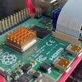
Here we are using Wio-E5 board. So in this we are using the AT command capability of this board. In-order to use AT command firmware we need an another microcontroller having two UART communication ports. Here Raspberry Pico is used as the Host microcontroller.
A small breakout board designed for the Wio-E5 module is shown below.
Now connect the Wio-E5 module to the Raspberry Pico, the circuit design is shown below.
Here is an example,
After connecting to the Raspberry pico, the working of the board could be checked using the AT commands.
Upload the given code to the Raspberry Pico for checking working condition of the board.
void setup() {
  Serial.begin(9600);
  Serial2.begin(9600);

}

void loop() {
  while(Serial.available()>0{
    Serial2.write(Serial.read());

  }
  while(Serial2.available()>0){
    Serial.write(Serial2.read());

  }

}
Open a serial tool(eg. Arudino Serial Monitor), select the right COM port, set baudrate to 9600 and select Both 'NL & CR' and Send 'AT' if working condition is satisfactory "+AT: OK" is displayed on the serial monitor.
Here some example AT commands to test the LoRa communication, which were used in the project.
AT+MODE=TEST      // LoRaWAN modem enter TEST mode successfully

AT+TEST=?         // Query test mode and RF configuration

AT+TEST=RFCFG,[F],[SF],[BW],[TXPR],[RXPR],[POW],[CRC],[IQ],[NET]  // for configuring

AT+MODE=RXLRPKT   // Continuous receive pure LoRa packet, print once there is new packet received
Here is the sample video showing the successful data receiving when LoRa Communication is established.
When the serial monitor prints the Received data, turn it in to our required format.
Real-Time Map GenerationI the Received GPS coordinate into usable format like this, S coordinates. Here folium is used for generating the Real-Time Map and it is implemented with the help of Flask based web app.
Here the turned the Received GPS coordinate is converted into usable format like this.
N1 denoting "GPS Node-1" and other are just coordinates and status signal.
By using PySerial library we can put this output to the python file in order to make a simple implementation of the live Map.
You can install PySerial by using this command.
pip install pyserialThis line will read the data from receiver.
received_data = serialData.readline().decode('utf-8').rstrip()Example code for Serial reading.
def collectData():
    serialData = serial.Serial('COM8', 9600, timeout = 1.0)
    sleep(2)
    serialData.reset_input_buffer()
    print("----collecting----")
    while True:
        sleep(0.01)
        if serialData.in_waiting >0:
        myData = serialData.readline().decode('utf-8').rstrip()
        # print(myData)
        data = myData.split(",")

        if len(data)>0:
            print("----collected----")
            break
return data,receiCord
after getting GPS coordinate we have to create map, so we need folium.
To install folium follow the command.
pip install foliumHere is the example of giving coordinates
import folium

m = folium.Map(location=[45.5236, -122.6750])
m
This will be the output
We can save the generated map as 'html' file.
m.save("index.html")So, next step is to integrate all this in the python file and the python file will generate an interactive map with a webpage. It will refresh automatically when new data is received.
Example code for live Flask GPS web page.
@app.route('/')
def index():
        global bLat,bLon,iLat,iLon
        iLat,iLon,bLat,bLon = get_data()
        distance = getDistance(node=(iLat,iLon),boat=(bLat,bLon))
        print(distance)
        colour = checkBoundary(distance)
        print(bLat,",",bLon)
        folium_map = folium.Map(location=(bLat,bLon),zoom_start=16)
        folium.Circle(location= (bLat,bLon),radius=40).add_to(folium_map)
        folium.Marker(location= (iLat,iLon),popup="Timberline Lodge",icon=folium.Icon        (color=colour)).add_to(folium_map)
        print("loading...")
        g = folium.GeoJson('world.json', name="geojson").add_to(folium_map)
        folium.GeoJsonTooltip(fields=["name"]).add_to(g)
        folium_map.save('templates/map.html')
return render_template('index.html')

@app.route('/map')
def map():
return render_template('map.html')
When we get the coordinate, it will be displayed on the map.
Codes are uploaded at GitHub.
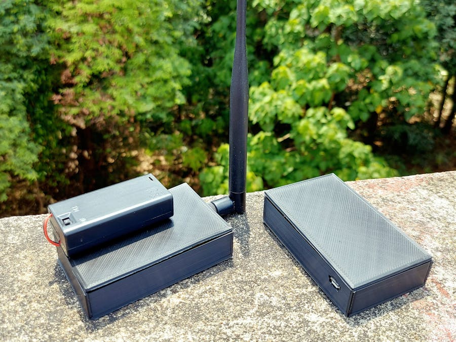
Finally, a pragmatic case to incorporate the project was 3D printed.
All modules were arranged in the 3D printed case.
This is the receiver,
The whole working is briefed in the video given below.
Seeed Studio CO-CREATE
Also, they are currently running a co-creation campaign that lets you launch your idea into life.
All licensed projects, whether hardware, software, tutorials, or complete products, will feature on the Seeed Studio store (Bazaar) individually or with Seeed Studio's products for sale, and you will get a share of the profits. We are looking for unique projects that strongly identify with Seeed Studio's audience, solve real-life problems, fill a niche, and/or spur inspiration and creativity. Find out how you can co-create and license your ideas and talents with us now: https://www.seeedstudio.com/co-create.html


Comments