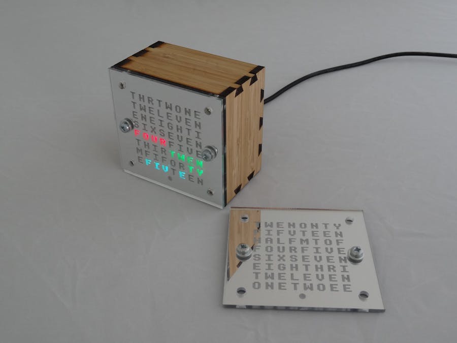
Every Maker needs to create a Word Clock. This is mine.
The salient points about this build are:
- Two interchangeable face designs
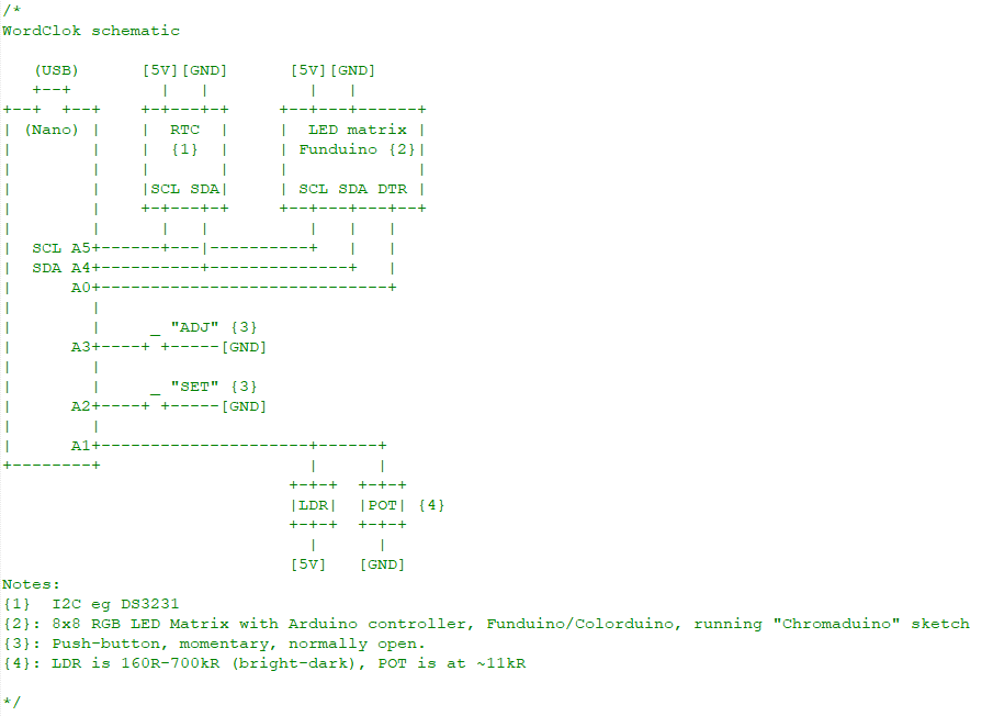
- 8x8 RGB LED matrix with its own Arduino controller, slaved to a master Arduino
- Laser-ablated face-plates
- Laser-cut dovetail-joint enclosure
- The display can be configured to dim in low ambient light
Finding someone selling "Funduino" 8x8 RGB LED matrices on TradeMe (New Zealand's eBay) was the motivation for starting this project. The seller didn't know much about them, nor did Google, but I ordered some anyway. Out of the box, they did not work: when powered on, they showed weirdly changing patterns. Eventually I determined that the LED matrices had been socketed onto the controller boards 180 degrees out (I suffered so you don't have to: pin 1 on the matrix goes to Blue pin 1 on the board.) I also determined that the boards were just programmed to run a demo. So I wrote my own simple slave program (Chromaduino). Based on the "Colorduino" demo but simpler and perhaps clearer, it drives the LEDs and receives display information from a master over I2C. The Chromaduino code can be found on Github.
I spent a lot of time playing around with the arrangement of the letters on an 8x8 grid. It was an interesting and enjoyable challenge, a little like a reverse cross-word puzzle. In the end I came up with two designs. Both tell the time to the nearest 5 minutes with no AM/PM indicator. The first face ("Half Ten") shows the time as MINUTES TO HOUR or MINUTES OF HOUR, for example FIFTEEN TO TEN (at 9:45) or FIFTEEN OF TEN (at 10:15).
"Half Ten" face:
 TWENONTY
 FIFVTEEN
 HALFMTOF
 FOURFIVE
 SIXSEVEN
 EIGHTHRI
 TWELEVEN
 ONETWOEE
The second face ("Ten Thirty") simply shows the time as HOUR MINUTES, for example TEN FIFTEEN (at 10:15). Rather than show the hour as a bare TEN, they optionally show it as NONE OF TEN and TEN EVEN respectively. Also TEN FIVE looks odd, so I throw in a "O" for TEN O FIVE (the latter was a last minute thing).
"Ten Thirty" face:
 THRTWONE
 TWELEVEN
 ENEIGHTI
 SIXSEVEN
 FOURFIVE
 THIRTWEN
 MFIFORTY
 EFIVTEEN
Because the words are sometimes adjacent, the design works best with colored LED's, to distinguish them. I am happy with the two faces: they are complete (all the hours, all the five-minute intervals), they fill the grid (there's one unused location in both grids, here occupied by an 'M') and they're quirky (TWEN TY etc). I couldn't decide which I liked better. I toyed with the idea of making two clocks, but in the end decided to make the face interchangeable. The face-plates snap onto the front of the enclosure, held in place by magnets. A chorded button-press toggles the display mode.
This is tricky. How to make good-looking letter-shaped windows in something practical and attractive, and have the LED's shine through them without too much spill-over to adjacent letters? My go-to solution was to laser cut something (I use Ponoko). I considered using a stencil font to cut through an opaque material. I wondered about etching normal letters onto a transparent material, somehow carefully peeling off the etched-through protective backing leaving letter-shaped islands, spraying the exposed material with an opaque paint, then peeling off the remaining backing. Nothing seemed very appealing/practical. Then I noticed that a mirror material was available. This was the answer I was looking for! It is opaque, but the laser can ablate the mirror coating off the back, leaving a translucent window. No need for a stencil font. My laser cutting designs are written in Python for Inkscape. For ultimate control I created my own stroked font code from the venerable BBC Micro bit-mapped font. Since I was using a sheet of Mirror for the faces, I also used the rest of the sheet for some other parts of the assembly, most importantly a "cell" layer. This has a grid of square windows cut out of it and is sandwiched between the LED matrix and the face plate. While it still had its protective layer on, I spray-painted it obliquely, to cover the transparent internal sides of the windows. It does a reasonable job of limiting bleed-through.
I used my technique for producing dovetail joints from laser-cut bamboo to make the enclosure. This is explained in my flickr set (laser-cut tail and notched pin, use a chisel/blade to slice a triangular piece off the pin, along the grain)
The whole thing sandwiches together with bolts running from the front and the back with standoffs between.
There are two buttons: Set and Adj.
- Pressing Set sets the time, then Adj increments the minute or hour, Set accepts it.
- Pressing Adj cycles through colour modes: RGB, reds, greens, blues, white(ish) and random. Unless the current time is on the hour, in which case it toggles showing NONE/EVEN
- Pressing and holding Set sets the display dimming, first the ambient level to "DIM AT" then the brightness to "DIM TO"
- Pressing Set and Adj cycles through display off and alternate faces
- Holding Set at power on runs the LED matrix demo
- Holding Adj at power on runs the clock in demo mode
- Holding Set and Adj at power on resets the clock configuration
Power is via a USB cable and wall-wart, which also lets me perform post-assembly re-programming. After assembly I replaced the DS1307 RTC board shown in the photos, which lost 7 seconds a day, with a DS3231-based board.
There's a flickr set with a few more photos.


_3u05Tpwasz.png?auto=compress%2Cformat&w=40&h=40&fit=fillmax&bg=fff&dpr=2)
Comments
Please log in or sign up to comment.