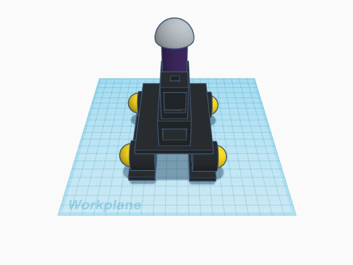
This is a cheap, easy to make robot. It can sterilize your room with UV-C light, it is light and agile, it can go on any terrain, and it can fit in any doorway. It is also human-safe, and fully autonomous.
Step 1 :To start off, I am on a really low budget, so I couldn't get a UV light :(
Second, my camera has a lens problem, so I apologize.
Let's get started!
Build your Black Gladiator Chassis and fit the tracks to it.
This is the hardest part.
Because there are so many wires, I didn't make a circuit diagram, but the list below shows the pin numbers.
Pin Numbers:
- "R" pin of your SMD RGB LED to pin 2 *
- "B" pin of your SMD RGB LED to pin 3 *
- Output of your PIR to pin 8
- Trig of your HC-SR04 to pin 9
- Echo of your HC-SR04 to pin 10
- Switch of your relay to pin 11
DRV8833 Pins:
- AIN1 to pin 4
- AIN2 to pin 5
- SLP to 3.3 V
- BIN2 to pin 6
- BIN1 to pin 7
- AOUT 1 to Left Motor, Labeled Side
- AOUT 2 to Left Motor, Unlabeled Side
- BOUT 2 to Right Motor, Unlabeled Side
- BOUT 1 to Right Motor, Labeled Side
- Another thing about the motor wires - make up some alligator clip jumpers like I did here, put a breadboard jumper cable in one clip, and attach the other clip to the motor terminal. Do this for all four wires.
UV-C Light Wiring:
- Connect it to the relay like this (just don't do the ESP or circuit board).
* Connect all three wires to one breadboard bus and link one other wire back to the respective Arduino pin.
Follow the pictures of what it should look like.
Put standoffs in 4 holes on the chassis. Screw the nuts on the bottoms. Then make holes that align with the standoffs on a flat piece of cardboard that should be a little bigger than the chassis itself.
Screw the screws in the top of the cardboard holes and standoffs.m
Look at the pictures to see what I mean. A picture is worth a thousand words, right? :)
Cover the cardboard box with black construction paper, like in the picture. Put the small cardboard box on the front of the top and glue it in. Make sure you cover the hot glue with paper, too! Picture 5 is before covering, Picture 6 is after.
Drill a hole in the bottom and top of the small cardboard box. Then drill a hole in the top of your large cardboard box that is in exactly the same spot as the hole in the bottom of the small cardboard box. This hole is for the wires of the PIR sensor and SMD RGB LEDs.
Refer to the pix for more.
Cut a rectangle in the front of the large box for the ultrasonic sensor.
Cut a hole in the front of the small box for the PIR.
Put a aluminum foil baffle on top of the UVC light.
Coding:Disable the SLP pin, so your robot doesn't run away while uploading. Upload the code to the Arduino Nano.
Code your Microbit with the code below in Mu. Mu should be in micro:bit mode. It tells you how many times it turns left if you press button A, right if you press button B, and how long it has been operating if you press A & B. Just don't tilt it when you are pressing!
Enable the SLP pin, place your powered-down robot on a cleared floor surface, turn it on, and exit the room.
If all goes well, the robot should wait for 30 seconds until you exit the room, calibrate it's PIR sensor, and start disinfecting. If a human enters the room, it will shut down immediately.
The specs are in the linked GitHub repository.
Disclaimer:
If anyone is blinded, burned, or injured in any way, or if damage is caused to pets, property, or any other thing, I am not responsible, liable, or required to make any reparations for the damage.
If your Robotic Disinfection System works, congratulations!
If it doesn't, reread the wiring step.
Thanks for reading!
Merry Making,
g3holliday


_XKWXdjKhBq.png)


_3u05Tpwasz.png?auto=compress%2Cformat&w=40&h=40&fit=fillmax&bg=fff&dpr=2)
Comments
Please log in or sign up to comment.