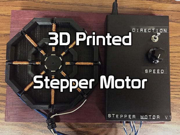
I recently came across this instructable of a 3D Printed DC Motor and I figured I could take it a step further; Literally. I designed this stepper motor with eight electromagnets, six neodymium magnets, with a 3d printed rotor and stator housing. This is specifically a permanent magnet stepper motor capable of 15 degree full steps and 7.5 degree half steps. There are many different types of stepper motors but most of them work very similar to the one I have designed here. This is an educational display to show others how stepper motors work. I designed this to run on a 5-12VDC power supply so it will work with most USB power supplies.
I am also doing a giveaway on my Youtube channel. I will be giving away an arduino, transistors used in this project, and some switches. More details in the last step.
Step 1: What You Will Need
- Six 1/4" neodymium magnets
- 608ZZ Bearing
- Eight 8d 2-3/8" nails - Not critical what nails you use as long as they fit.
- Magnet Wire - I used 0.315mm magnet wire but this is not critical.
- Arduino Uno
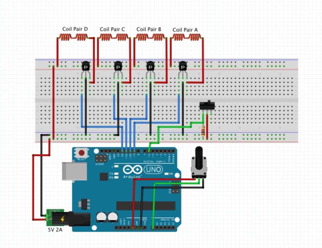
- Four Transistors - I used PNP transistors I had lying around, but you can use whatever transistors you want or MOSFETS as long as you make sure they can handle the current your motor will draw. Read the datasheet carefully for specific recommendations. On 5v mine motor draws about 1 amp and on 12v it demands about 3 amps.
- 3D Printed Rotor and Stator
- Glue
- Electrical Tape
- A compass
Step 2: Print The Dodecagon Rotor and Octagon Stator
Print with 3D Hubs!
Step 3:
Use a compass to determine the poles of your magnets and glue the magnets with the north poles facing outward. If your magnets are strong enough, the compass on some smartphones will show you the polarity of the magnets.
Step 4:
Press fit the bearing into the stator and then press the rotor into the bearing. I was pleasantly surprised how well the bearing press fit into the stator. When 3d printing, holes tend to want to shrink inward and end up smaller than expected so I usually oversize them a bit.
Step 5:
Cut 9 pieces of wire to 25 feet and wind them with a drill. Use a compass and a battery to determine the configuration required to give you the south pole at the head of the nail. Use a marker or heat shrink tubing to mark the negative lead of your electromagnets. Wrap the sections of the electromagnets with electrical tape where they will come in contact with the stator housing. This serves two purposes. It firmly secures the electromagnets in place and also insulates the housing from any heat the coil may produce. The coil pairs draw about 1 amp with the 5V power supply I am using. The transistors I chose can handle using a 12V power supply that the coils draw about 3 amps from. The problem with the higher voltage supply is that if I leave it running for a bit, the coils start to get warm.
Warning:
I designed this to run on a 5-12VDC power supply. If you decide to stray off the beaten path, use Ohm's Law to determine what size coils you want. V = I*R
Remember, the fewer windings on your coil, the lower the resistance is going to be. If you are not careful, your coils will pull more current than your power supply or transistors can handle and bad things will happen.
Step 6:
Push the electromagnets into the stator until they're about 1/4" from the neodymium magnets. You can slide the electromagnets in and out as you wish, but I didn't want them too close because the nails will become magnetized much faster. That's the downside of using the nails. The motor will still work once they become magnetized, but it will be less efficient. Welding rods are a good alternative to the nails if you have some laying around.
Step 7: Solder Everything Together
Wire up your coil pairs in series and connect them so that all the south poles of the electromagnets face inwards. The resistor I used in the schematic is a 1k resistor. The purpose of this is to prevent the digital pin from "floating" high when in the off position. Again, make sure to use a transistor capable of holding up to the current that your coils will be demanding.
Load the source code to you arduino and you're ready to go!
Step 8: Pay It Forward!
I will be giving away an arduino, the transistors used in this project, along with some switches and jumper wires.
Rules for the giveaway:
Subscribe to my YouTube Channel, like this video and leave a comment on the video saying what you would like to see me build next. On September 1st I will randomly select a subscriber's comment and ship them out for free! Thank you guys for being such a welcoming community!


_ztBMuBhMHo.jpg?auto=compress%2Cformat&w=48&h=48&fit=fill&bg=ffffff)


Comments
Please log in or sign up to comment.