Back in February of 2017, I created a project that showcased how to construct an LED matrix with neopixel strips. It did have a few problems, however, as it lacked a proper power supply and looked terrible.
This time around, I wanted to make something bigger and better. Namely, a 20-by-15 matrix behind a nice panel that hides everything except the LEDs themselves.
A strip of neopixels is one-dimensional, so how can it be a matrix? By chaining several strips in rows and calculating the pixel’s index from X/Y coordinates, a matrix can be simulated. The strip is still one-dimensional, but since there are now rows and columns, it appears to be 2 dimensional.
Neopixel strips usually have many WS28xx LEDs on a flexible PCB.
They receive color information through one wire with a clock speed of 800KHz. Data is cascaded down the strip, so pixels have no individual addressing, but instead “take” the first set of 24 bits and pass the rest down the strip.
This means all pixel data has to be stored and manipulated in RAM and then pushed to the LEDs when requested.
Making a FrameBefore any cutting can be done, some dimensions have to be taken. The LED strips I chose have a density of 30 pixels/meter. I measured the distance between pixels to be about 33.5mm, which is equal to 1 5/16 inches. Since I am using 300 neopixels total, I decided to make my matrix 20 pixels wide and 15 pixels tall, which means it takes up an area of 67cm by 50.25cm. After marking that on a sheet of plywood and creating a margin of 2 inches, I cut the sheet to size.
Next, I drew a grid with a spacing of 33.5mm and marked an ‘X’ wherever a 5/16in hole should go for the pixel to show through. Drilling 300 holes took a while, but after a thorough sanding, it turned out great.
Neopixel strips have pads near each LED that lets it be cut and soldered, so I cut each strip every 20 LEDs.
Each LED has a little arrow that indicates the direction of data, so they must all point the same way when being attached. I used hot glue as my adhesive of choice due to its ease of use and it allows for the strips to be removed if necessary.
At full brightness (brightness = 255 and color = white), each LED can draw 60mA, which means all the LEDs can draw up to 18A! This might seem like a lot, and it is, but by changing the brightness, the current draw can be changed. The LEDs are still very bright at 1/5 brightness, and it also means the max current draw will be 3.6A. I still went with a 5V 10A power supply to allow for some more headroom when setting the brightness.
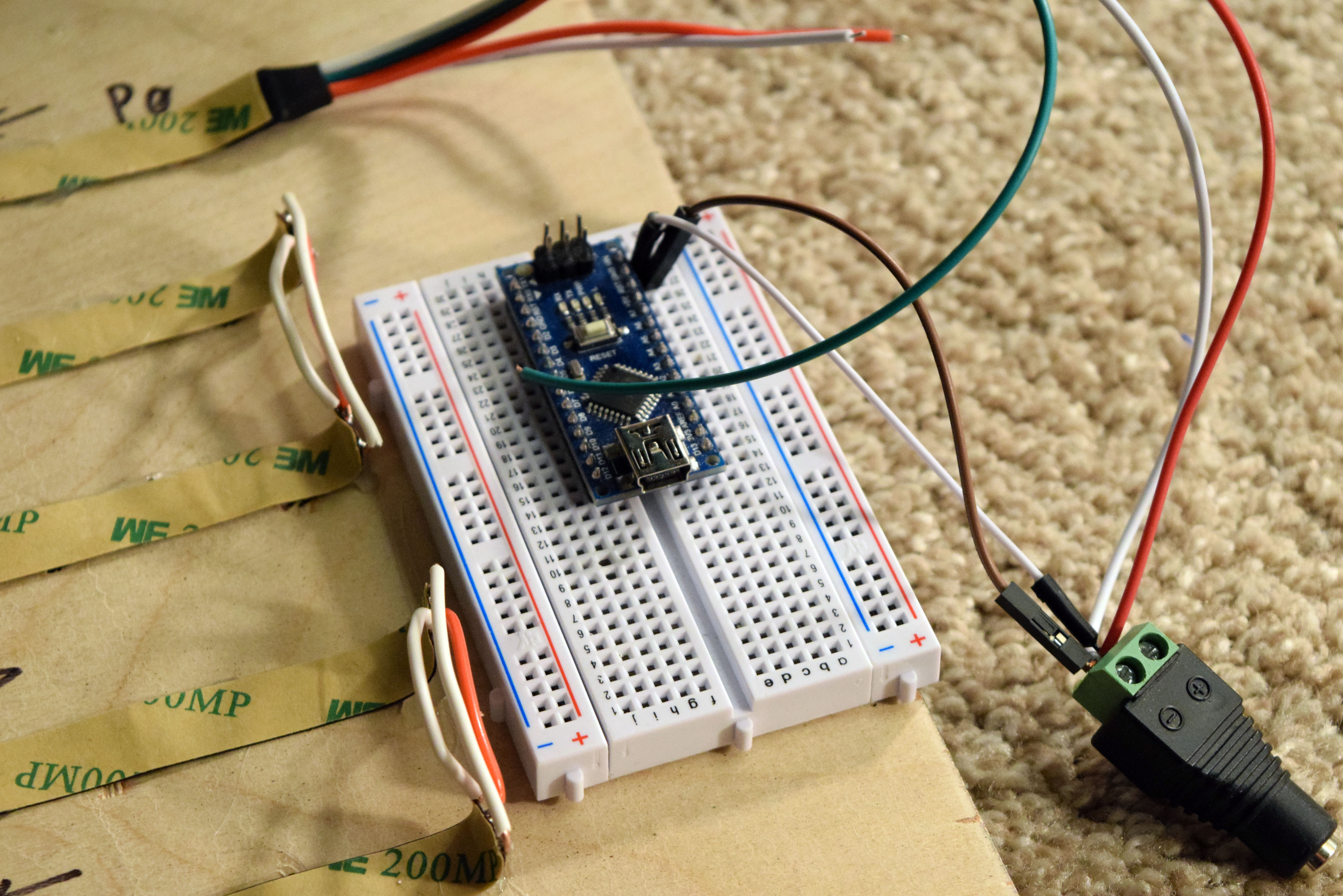
Controlling the MatrixThe data pin for the WS2812b LED requires a minimum voltage of 3.5v, which means that 3.3v microcontrollers cannot be used without level shifting. That is why I went with the Arduino Nano to control the matrix for now.
Adafruit has a great neopixel library to control the pixels, and it also has a neomatrix library for controlling pixel matrices. This lets you use the Adafruit GFX API to draw text, graphics primitives, and even images with ease. This project’s attached code displays several different LED patterns that change over time.
Possible UpgradesIn the near future I plan on switching out the Arduino Nano with either a Particle Photon or Teensy 4. The Photon has WiFi connectivity which would enable the matrix to display data such as weather or notifications. Due to its powerful processor and large amount of RAM, the Teensy 4 would be a great choice to display a game on the matrix.


Comments
Please log in or sign up to comment.