It’s always fun to build a robot, but eventually little car kits and basic servo walkers get boring.
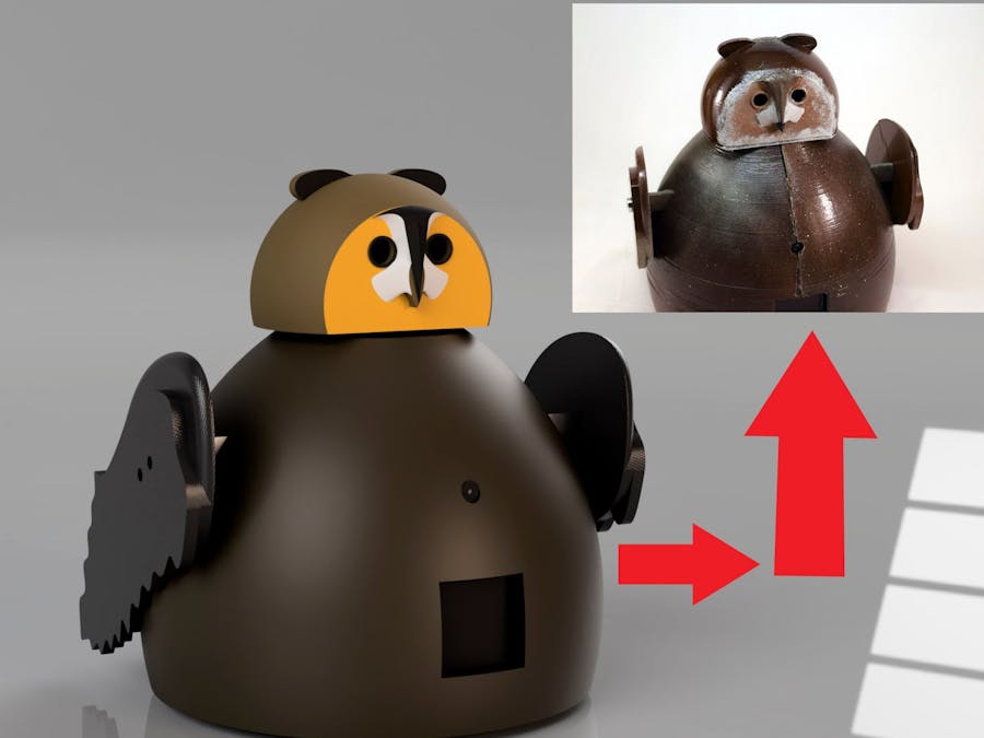
That’s when it becomes necessary to design and build your own chassis that can perform custom functions and contains anything you want. For this project, I decided to build a robot that looks like an owl and can take pictures and display information on a built-in screen.
Before anything can be designed, a basic plan must be created. This includes functionality, size, looks, and other features. I wanted my robot to look like an owl, be able to move, take pictures, and have a screen. For the size, I settled on a height of around 20-30cm, and a width of about 15-25cm. The screen would have to be positioned in the front, and the camera would need to be either just above or below the display.
Select ComponentsNow that the planning had been completed, it was time to choose which components to use. For the “brain”, I settled on a Raspberry Pi Zero Wireless due to its small size, compatibility with cameras, and plenty of GPIO to drive a screen and motors.
I opted to use DFRobot’s 128x128 OLED screen as the display, and also their Raspberry Pi-compatible camera module. Because I wanted precise control over movement, simply using a couple of DC motors wouldn’t cut it. Instead, I chose two NEMA17 stepper motors and two L293d dual H-bridge motor driver ICs.
To build the body, I started by placing components in the general area where I wanted them in Fusion 360. The motors would have to go near the base, and the screen and camera would need to face the front and be close to each other.
Next, I sketched a rough outline of a body that would surround the components and form the frame. Fusion 360’s revolve tool enabled me to quickly create a shell.
For the head, I took a picture of an actual owl and inserted it into the design using the Attached Canvas tool. From there, I traced the shape of the head and beak and used the loft tool to extrude them into 3D objects.
Finally, I wanted to add wings to each side for a more natural look and to break up the exterior. By using a similar method of tracing and extruding, I was able to make cartoon-looking wings.
I chose to use 3D printing to fabricate the body panels. I first exported the.STL files using the Make tool in Fusion 360 and then loaded them into XYZWare’s 3D printing software.
For printer settings, I went with a layer height of.25mm and a speed of around 35mm/s. I wanted to use PLA for this print due to its flexibility and tendency to not warp. Once each part was printed, I sanded it and then spray-painted layers of almond white, black, and brown for a more natural look.
Since everything had already been laid out in CAD, assembly was very easy. I simply used 3mm screws to attach each component to the body, and then glued the two halves, along with the head, together.
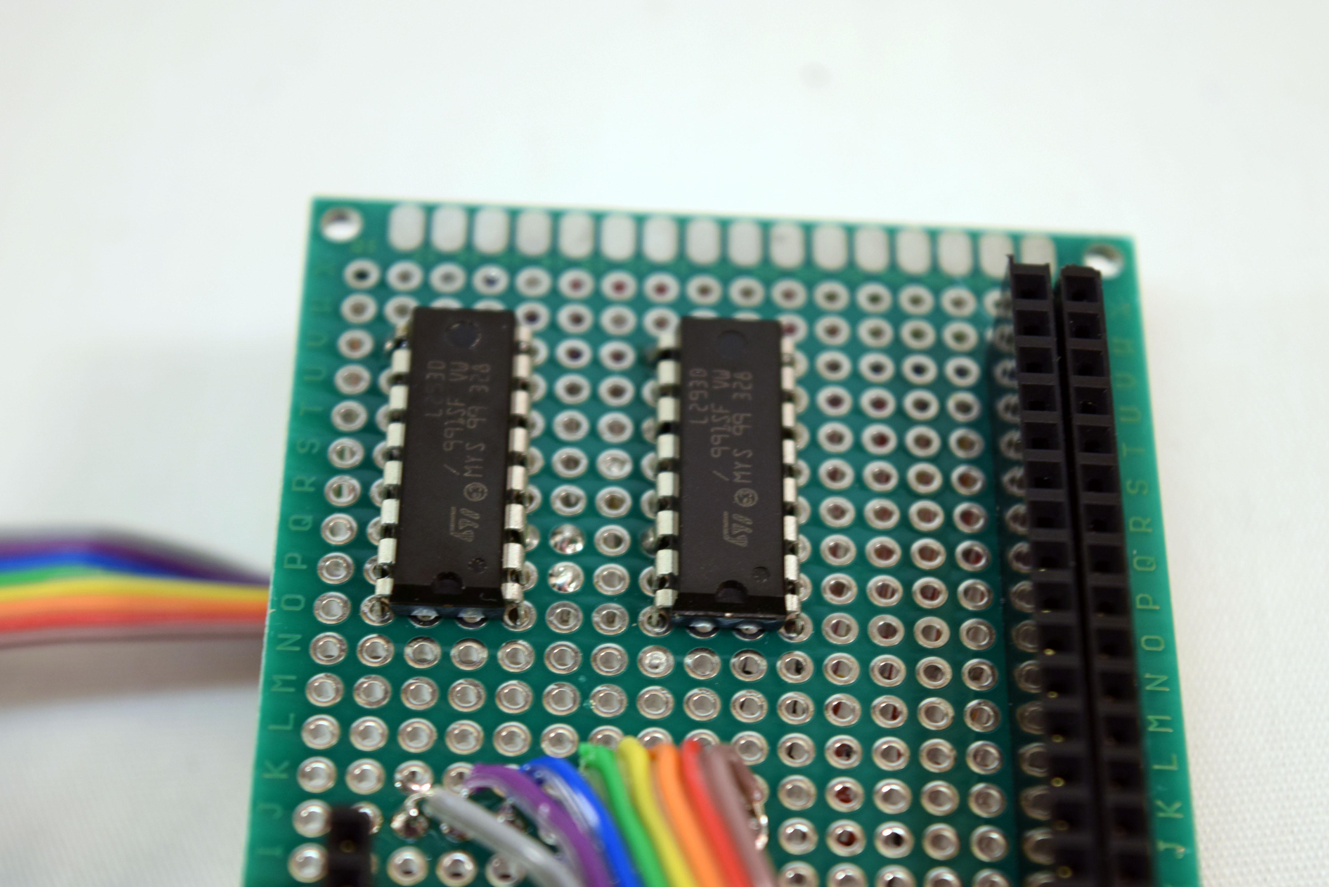
Those are the basic steps for creating a custom robot chassis. I later went on to solder a protoboard together with two L293d motor drivers, along with connections for the OLED screen and stepper motors.


Comments
Please log in or sign up to comment.