This project was created as a throwback to a much simpler toy, the Etch-a-Sketch, but instead of moving a tiny stylus to wipe aluminum particles off of a glass surface, this one plots pixels onto an RGB matrix.
I tried to remain true to the design by adding the ability to clear off the screen by shaking the device.
A DemonstrationDesigning and Fabricating an EnclosureI made it a point to model the Pix-a-Sketch after the actual Etch-a-Sketch toy, including the size, knobs, and position of the "screen". I began by using Fusion 360 to model each component, such as the matrix and rotary encoders. Then they were placed onto a virtual plywood board and had a plastic frame built around it. Each piece was 3D printed in PLA, and then the bottom wooden board was cut with a CNC router.
Below is a render of the final iteration.
You have probably heard it a thousand times by now, so just go view a guide on how to set up your Raspberry Pi here.
After connecting it to a WiFi router, install the rgb-matrix library by following the instructions below:
Just run
curl https://raw.githubusercontent.com/adafruit/Raspberry-Pi-Installer-Scripts/master/rgb-matrix.sh >rgb-matrix.sh
sudo bash rgb-matrix.sh
Then press y to continue and choose option 2 to select the Adafruit Matrix HAT.
Then choose number 2 to free up pin 18 so that sound can still be output over the audio jack.
To test it go into the examples-api-use directory and run
sudo ./demo -D0 --led-rows=64 --led-cols=64 --hardware-mapping=adafruit-hatYou should see the demo running. Just hit ctrl-c to exit it.
You will also need to install the mpu6050 library with
pip3 install mpu6050-raspberrypiand then add the user root to the i2c and gpio groups.
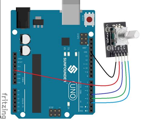
Reading Encoder DataBecause the RGB matrix takes up so many GPIO pins, using four extra GPIO pins for the two rotary encoders was out of the question, so I had to get a bit creative.
To solve this problem, I used an Arduino Nano as an I2C slave device that would be able to count the rotations of each encoder and then send that information to the host device when requested. Upon each request for encoder data, the total number of rotations is set back to zero, which gives relative positional data rather than absolute positioning.
Displaying an ImageThe Python script begins by initializing the matrix, including information such as size, number of panels, and the pins it uses. Then, the two I2C devices are initialized and reset, along with a hardware push-button switch. Then the update() function is called repeatedly, which is similar to Arduino's loop() function. It reads in new encoder data, finds where the new position should be, and then moves the cursor to there.
If the device detects it is being shaken, 5 random lit-up pixels are selected and then turned off. To erase the entire matrix and return the cursor to its origin (0, 0), the hardware button can be held down for two seconds.


Comments
Please log in or sign up to comment.